Device connections – TEKVOX TekMonitor 2 User Manual
Page 21
TEK 2
User’s Manual
V111813
21
TEK
VOX, Inc. – 210.348.6565 –
San Antonio, TX 78216
Most manufactures use a DB-9 type control connection and it is not always easy to determine if pin 2 or 3
is the transmit pin. An easy way to determine which is the transmit pin is to use a DC volt meter and
connect the leads between pins 5 Ground and pin 2 or 3. The pin which has between 5 and 12 volts is the
transmit pin. Connect this pin to the Receive (RX) input on the TEK 2. When both transmit and receive
connections are made correctly on the TEK 2, you should be able to register between 5 and 12 volts
between Ground and the TX pin and Ground and RX pin on the TEK 2. Of course power must be on for
both devices.
Wiring connections can be found in driver information located in TekWizard.
Device Connections
The following is a list of wire diagrams for different device manufactures including both a direct
connection or through TekSecurity.
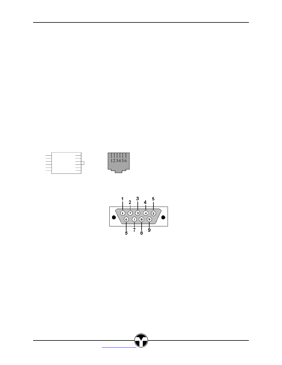
All Connector views are from rear of the connector.
TekSecurity RJ12 Pin out
The view of the RJ12 Jack is from the front. The TekMonitor side requires a six conductor cable. The
Device side requires a four conductor cable.
WHT 1
BLK 2
RED 3
GRN 4
YEL 5
BLU 6
RJ12 Plug
RJ12 Jack
PC DB-9 FM
TEK 2 PC
GND-----5
RX-------3
TX-------2