General specifications, Location of the antenna, Orientation – Televes Omninova BOSS (VHF/UHF) KIT User Manual
Page 21: Location of the control module of the antenna, Compatible accessories, Installation diagram
21
EN
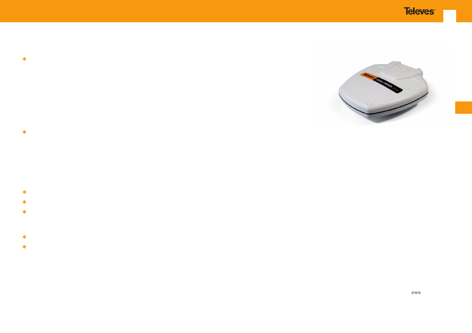
General specifications
Omni-directional antenna that can receive
television with stable images, regardless of
movement of the antenna.
The antenna incorporates the BOSS-Tech
innovative system which adjusts at all times and
once activated, the output signal of the antenna
so that its level is the adequate one regardless
of the signal variations due to movement of the
antenna or through areas of little coverage.
Maximum optimization of the gain of the
amplifier:
- By the selective amplification of the frequency
bands (FM, BI, BIII, UHF).
- Incorporating filters that reject signals from
other frequency bands, and especially marine
telecommunications bands.
Allows reception of AM radio signals.
Is protected against lightning.
UHF amplifier with BOSS-Tech technology, which
regulates every time the output level of the
antenna.
Watertight.
Complete kit includes everything needed for
installation:
- Network adapter.
- Cigarette Lighter Adapter.
- IEC type shielded connector.
- F type connector
- Control module of the antenna.
- Extender male / female of 1.5 m for connecting
the control module to the TV.
- Straight support .
- Angled support .
Location of the antenna
For mounting in vehicles, choose a location away
from electrical cables, motors, lighting systems and
electronic instruments (Fig. 1).
Generally, the most suitable location is near the
front of the vehicle, at the top.
For mounting on boats, the premise is to place the
antenna as high as possible, and as far away as they
can from other antennas and metallic parts of the
boat/ship.
Orientation
The antenna is omnidirectional, so it need not
be oriented for proper operation. However, we
recommend that is oriented in the opposite
direction of the march of the vehicle so that the
antenna provides the minimum wind resistance
(Fig. 2).
Location of the control module of
the antenna
Choose an accessible location inside the cockpit
where to place this module so that it is protected
from heat, moisture, ... and so on., ensuring that
the cable length from the antenna to the control
module is not excessive. Also, should not be made
to the cable kinks or bites (Fig. 3).
Compatible accessories
Its mounting system is compatible with most
media that have a tube-shaped base with a
maximum outer diameter of 25 mm (Fig. 4). The
system output cable, inside the tube, protects the
antenna main connection optimally, both to the
inclement weather as to beatings and aggression.
Installation diagram
Follow the diagram in Figure 5 for installation.
Make sure the power is correct, either through
the network adapter or via the cigarette lighter
adapter for battery power: 11 ... 16 V
.