Identification of the system elements, Introduction, Dvbs2 - cofdm / cofdm ci – Televes DVB-S2 COFDM User Manual
Page 10
DVBS2 - COFDM / COFDM CI
10
channel (UHF or VHF and with a maximum
bandwidth of 8 MHz) using an agile up-converter.
Additionally, ref. 563301 incorporates a Common
Interface slot for inserting a conditional access
module (CAM) to permit the unscrambling of
services.
The DVBS2 transmodulator with COFDM CI receives
a satellite transponder in some DVBS (QPSK) or
DVBS2 (QPSK or 8PSK) modulation formats and
demodulates it by obtaining an MPEG-2 transport
package.
The MPEG2 transport package is then modulated
in COFDM format and converted to the output
The programming of the transmodulator operating
parameters (input frequency, output channel,
modulation format and adaptation of services
mainly) is performed through the universal
programmer (ref. 7234).
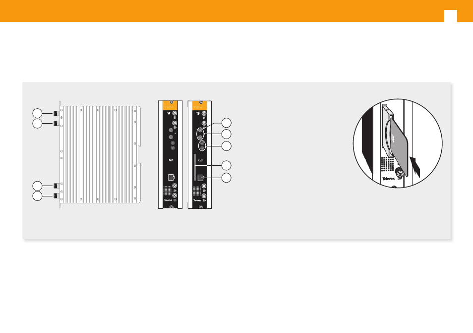
4. Identification of the system elements
4.1. Introduction
1
3
2
4
CAM
CTRL
PRGM
DVBS2-COFDM CI
PWR
6
7
9
5
8
UQC-S2-CI-S
UQC-S2-S
02340043001 003
CTRL
PRGM
DVBS2-COFDM
PWR
1. IF satellite input
2. IF satellite output
3. RF input
4. RF output
5. Module power supply input
6. Status LED
7. Control BUS connector
8. Input to insert CAM
(only ref. 563301)
9. Programmer / PC connector
CTRL
CAM PRGM
B
QPSK-PAL CI TWI
N
PWR
Insert the smart card completely
into the CAM slot before powering
modules. Card contacts looking
left and forwards when it is being
inserted.
Ref. 563301
Ref.
563101
Ref.
563301