Important safety instructions, Inputs/outputs/connections description, Introduction – Televes DVB-S2 COFDM User Manual
Page 6: Technical specifications, General installation conditions
DVBS2 - COFDM / COFDM CI
6
Important safety instructions
General installation conditions
• Before handling or connecting the equipment, please read this
manual.
• In order to reduce the risk of fire or electric shock, do not expose the
equipment to rain or moisture.
• Do not take the cover off the equipment without disconnecting it
from the mains.
• Do not obstruct the equipment’s ventilation system.
• Please allow air circulation around the equipment.
• The equipment must not come into contact with water or even be
splashed by liquids. Do not place containers with water on or near the
equipment if it is not adequately protected.
• Do not place the equipment near sources of heat or in excessively
moisture conditions.
• Do not place the equipment where it may be affected by strong
vibrations or knocks.
• This symbol indicates that the equipment complies with
the requirements of CE mark.
Inputs/Outputs/Connections description
The unit (Fig. 1) is provided with:
1. IF satellite input
2. IF satellite output
3. RF input
4. RF output
5. Module power supply input
6. Status LED
7. Control BUS connector
8. Slot CAM (only ref. 563301)
9. Programmer / PC connector
Introduction
The DVBS2 transmodulator with COFDM CI receives a satellite transponder
in some DVBS (QPSK) or DVBS2 (QPSK or 8PSK) modulation formats and
demodulates it by obtaining an MPEG-2 transport package.
The MPEG2 transport package is then modulated in COFDM format and
converted to the output channel (UHF or VHF and with a maximum
bandwidth of 8 MHz) using an agile up-converter.
Additionally, ref. 563301 incorporates a Common Interface slot for inserting
a conditional access module (CAM) to permit the unscrambling of services.
The programming of the transmodulator operating parameters (input
frequency, output channel, modulation format and adaptation of services
mainly) is performed through the universal programmer (ref. 7234).
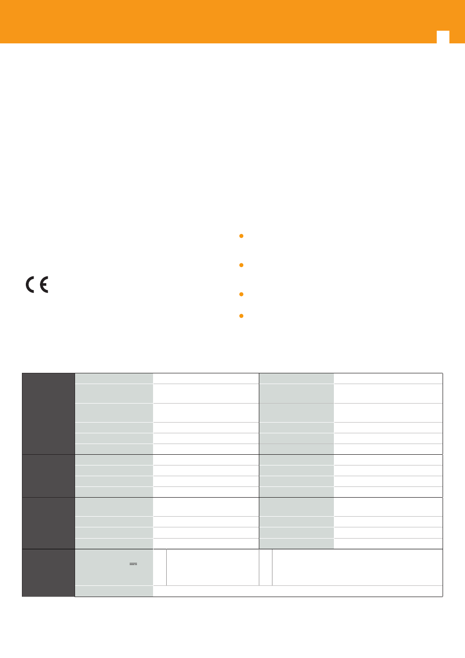
Technical specifications
Satellite
Demodulator
Input frequency
950 - 2150 MHz
Through loss
< 1,5 dB typ.
Symbol rate
10 - 30 Mbaud DVB-S2 (QPSK - 8PSK)
2 - 42,5 Mbaud DVB-S (QPSK)
Modulation
DVB-S2 (QPSK, 8PSK)
DVB-S (QPSK)
Frequency steps
1 MHz
Internal FEC
LDPC (9/10, 8/9, 5/6, 4/5, 3/4, 2/3, 3/5,
1/2)
Input/Output connectors
“F” female
External FEC
BCH (Bose-Chaudhuri-Hocquenghem)
Input impedance
75 ohm.
Roll-off factor
20%, 25%, 35%
LNB power supply
13/17V/ OFF 22KHz (ON/OFF)
Input VSWR
10 dB min.
COFDM
Modulator
Modulation format
QPSK, 16QAM, 64QAM
Scrambling
DVB ET300744
Guard interva
1/4, 1/8, 1/16, 1/32
Interleaving
DVB ET300744
FEC
1/2, 2/3, 3/4, 5/6, 7/8
Cell_id
Selectable
Bandwidth
7 MHz, 8 MHz
Output spectrum
Normal / Inverted (Selec.)
RF output
Output frequency
177 - 266 / 474 - 858 MHz (CH mode)
45- 862 MHz (frequency mode)
Through loss
< 1,5 dB typ.
Frequency steps
125 / 166 KHz
Return loss
> 12 dB typ.
Maximum output level
80 ±5 dBμV (progr.)
Input/Output connectors
“F” female.
Attenuation
>15 dB (prog)
Output impedance
75 ohm.
General
Consumption @ 24V
(with signal)*
563101
270 mA (LNB power OFF)
480 mA (LNB power ON)
563301
280 mA typ. (no CAM inserted; LNB power OFF)
330 mA typ. (CAM inserted; LNB power OFF)
500 mA typ. (no CAM inserted; LNB power ON)
540 mA typ. (CAM inserted; LNB power ON)
Protection index
IP20
* The unit’s consumption with CAM will depend on the type of CAM being used (only ref. 563301).
For the LNB it is considered a standard consumption of 300 mA.
The technical characteristics described are defined for a maximum ambient temperature of 45°C (113ºF). Forced ventilation is used for higher temperatures.