Vectronics VEC-1604K User Manual
Page 11
VEC-1604K Owner's Manual
Portable CD Amplifier Kit
9
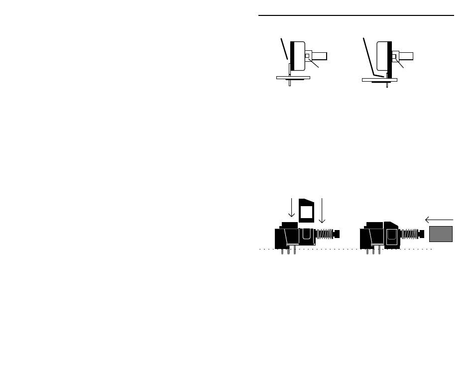
Rear pins use rear holes.
Front pins use front holes.
Nip off tab.
Nip off tab.
Find two (2) 10K potentiometers (marked B10K or B103K). Inspect for pin
location (as described previously) and locate the appropriate mounting holes on
the PC board.
! ! 25. Install a 10K pot at R1 and solder.
! ! 26. Install a 10K pot at R2 and solder.
Find the dual-section 500K pot (marked B504K). No alternative pin locations
are provided for this style control.
! ! 27. Install the dual-section 500K pot at R13 and solder.
Your kit contains a miniature DPDT switch. Some versions require installation
of a plastic clip-on support at the front of the switch body. This piece relieves
stress on the pins and ensures level seating during installation. If your parts kit
contains this piece, install as shown:
Your switch should also have a red cap supplied with it. Install this on the push-
button shaft. Once the switch is prepared for installation:
! ! 28. Install the DPDT mini switch at SW2 and solder.
The two last PC board mounted components are the AF amplifier ICs, U1 and
U2. Find these devices (marked TDA1013B). Before installing, inspect both
carefully and straighten any bent or crooked pins. Use extreme care during IC
pin insertion and move slowly. It's easy to miss a mounting hole and fold a pin
underneath the body.