Vectronics VEC-1604K User Manual
Page 12
VEC-1604K Owner's Manual
Portable CD Amplifier Kit
10
! ! 29. Find a TDA1013B and identify its keyed end. Now, find the mounting
holes for U1 and identify the keyed end on the silkscreen pattern.
Align U1 so it corresponds with the silkscreen pattern and insert,
checking carefully that all 9 pins enter their respective mounting holes.
Solder all 9 pins.
! ! 30. Repeat the above procedure, installing a TDA1013B at U2. Solder all
9 pins.
Installing the amplifier's power and audio connectors involves point-to-point
wiring, where you'll prepare and install installed wires connecting the jacks to
the PC board. Find the hookup wire provided with your kit. After cutting each
wire to its specified length, prepare it for installation by removing 1/4" of
insulation from each end.
Locate a 12" length of insulated wire:
! ! 31. Cut and prep a 2-1/2" length of insulated wire. Install one end at
GND4 and solder.
! ! 32. Cut and prep a 3" length of insulated wire. Install one end at GND3
and solder.
! ! 33. Cut and prep a 4" length of insulated wire. Install one end at GND2
and solder.
! ! 34. Cut and prep a 2" length of insulated wire. Install one end at GND1
and solder.
! ! 35. Locate the 2" length of red wire. Install one end at PWR and solder.
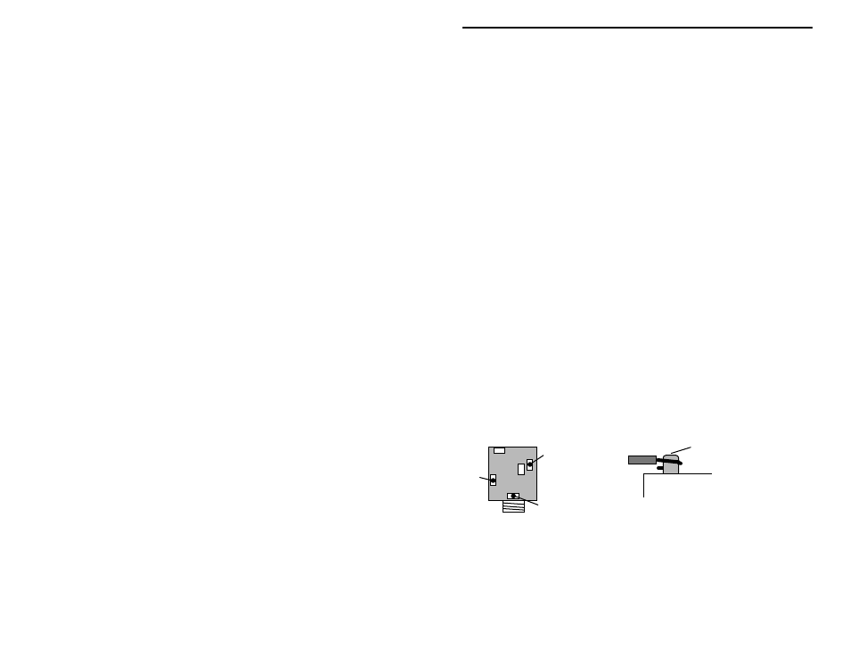
Locate three (3) 3.5-mm stereo jacks. Find the common (or GND) terminal
using the following diagram. Follow the installation detail when connecting
leads to jacks.
Tip
Common (GND)
Ring
Bottom View
Wrap lead-end around pin
and solder in place.
The first connector you'll install is the Left-Channel Speaker Jack:
! ! 36. Find the 2-1/2" insulated wire connected to GND4. Solder the free
end to the common or GND tab on a 3.5-mm stereo jack.
! ! 37. Cut and prep a 2-1/2" length of insulated wire. Connect one end to L-
OUT and solder.