Vectronics VEC-1604K User Manual
Page 18
VEC-1604K Owner's Manual
Portable CD Amplifier Kit
16
ENCLOSURE
To install your CD amp in the VEC-1604KC matching enclosure follow these
instructions (read all instructions before beginning ... take your time):
1. Find the front panel decal and trim. Be sure to leave excess decal material
around the edges. Put the front panel decal on. This is done by: a.) Remove all
debris and oil from the face plate. This should be done using a piece of cloth
and alcohol. b.) Remove the crack and peel to expose the adhesive. c.) Place
the decal on the front panel without securing it completely. d.) Gently rub the
alignment circles with your finger--if the circles are centered in the enclosure
holes (also check the corner alignment marks) secure the decal by rubbing and
removing all air bubbles. e.) If the alignment circles are not centered, adjust the
decal accordingly, then secure. f.) Use a penknife, or small Exacto
TM
knife, to
cut away the unused edges (cut from the adhesive side) and cut out the
component holes (cut from the description side).
2. Install the 2.1mm power jack. Find the two 3/8” small screws and the
appropriate nuts. Insert the jack so that the mounting holes line up, and tighten
the nuts onto the screws.
3. Now insert the PC board. This must be done by: a.) Remove the nuts and
washers from R1, R2, and R13. b.) Insert the front of the PC board so the
controls enter their respective holes. c.) Place the washers and nuts onto the
potentiometers and tighten. Ensure that the switch is aligned properly.
4. Install the three 3.5mm stereo jacks into the respective holes. This must be
done by: a.) Remove the nuts from J1, J2, and J3. b.) Ensure that the left
output (J2), right output (J3), and stereo input (J1) jacks are inserted into the
correct positions. c.) Place the nuts onto the three jacks and tighten.
5. Find the knobs. Now put the knobs on R1, R2, and R13. You may need to
loosen the set screw. Align appropriately then tighten the set screws.
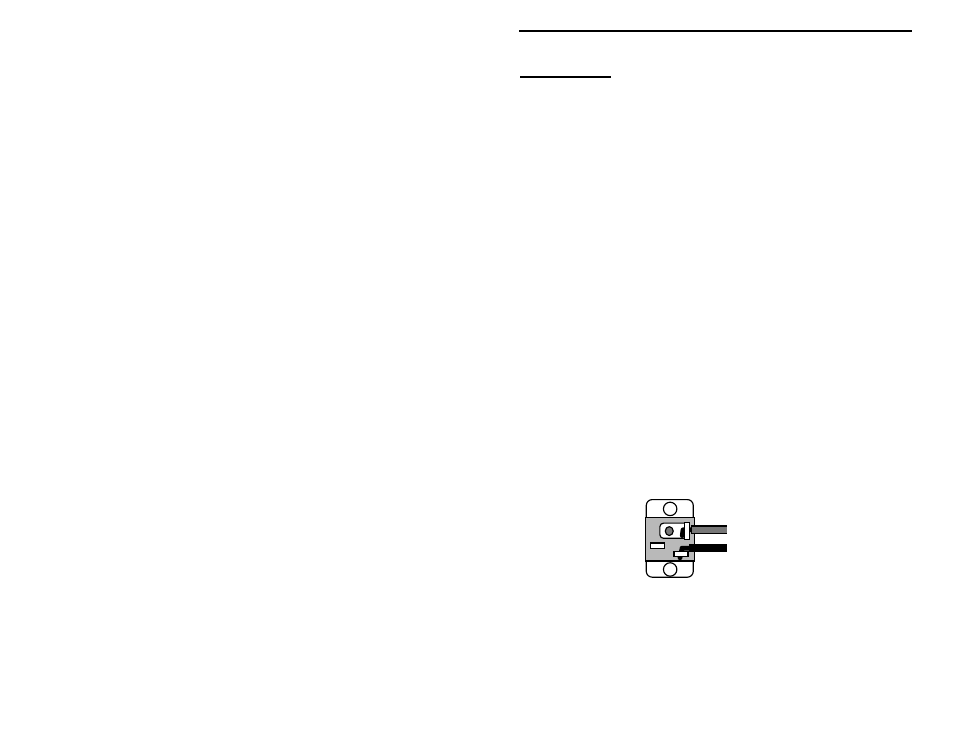
6. Next, solder the red power (PWR) and black ground (GND1) wires to the power
jack as shown in the following illustration.
red (+)
black (-)
7. Install the face plate into the plastic enclosure. Find the four 3/8” black
mounting screws. Insert the screws into the four mounting holes on the face
plate and tighten.
8. Finally, place the four rubber feet on the bottom of the enclosure at the corners.