Vectronics VC-300DLP User Manual
Page 3
VC-300DLP Antenna Tuner
Owner's Manual
3
COAX 2 selects the COAX 2 Connector, bypassing the impedance matching circuit but
providing normal meter readings.
TUNED MODE
COAX 1 selects the COAX 1 connector through the impedance matching circuit.
COAX 2 selects the COAX 2 connector through the impedance matching circuit.
WIRE selects the WIRE connector through the impedance matching circuit.
DMY LOAD selects the internal Dummy Load through the impedance matching circuit.
5. INDUCTOR
48-position rotary switch to vary inductance.
6. RANGE
Two-position push button switch selects the range of FORWARD and REFLECTED Power
displayed on the power meter.
When the RANGE switch is OUT, the FORWARD meter scale reads 300 watts full scale and
the REFLECTED meter scale reads 60 watts full scale. When the switch is IN, the
FORWARD meter scale reads 30 watts full scale and the REFLECTED meter scale reads 6
watts full scale.
7. METER
Two-position push-button switch selects PEAK or AVERAGE readings on the meter.
8. LAMP
Two-position push-button switch turns the meter lamp ON / OFF.
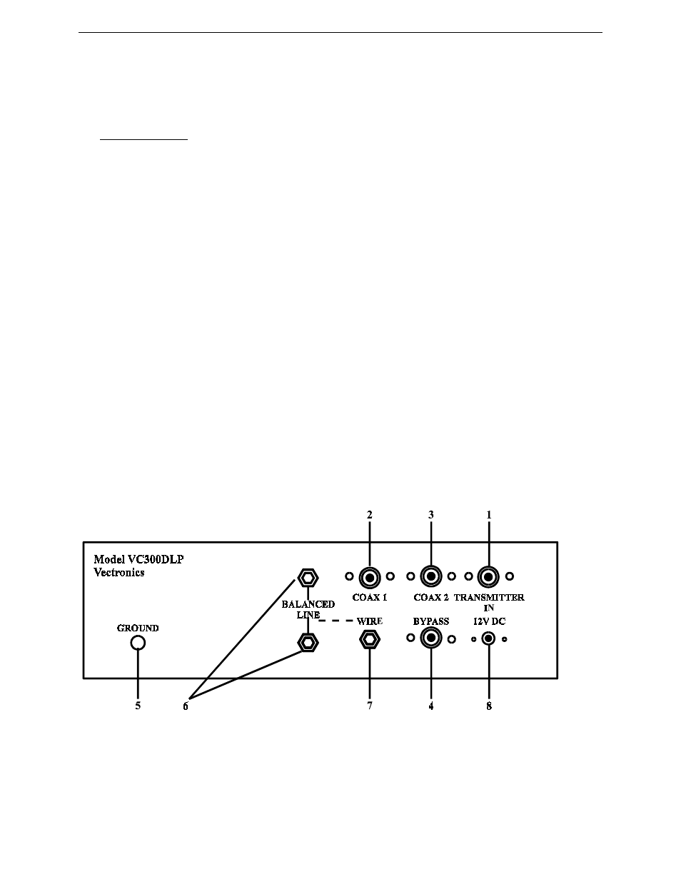
REAR PANEL CONNECTORS
1. TRANSMITTER
IN
Coaxial connector for input from SWL receiver or transmitter.
2. COAX
1
Coaxial connector for output to Antenna One.