Schematic diagrams, Zmotion, Detection module ii evaluation kit user manual 12 – Zilog ZEPIR0BA User Manual
Page 16
Advertising
UM026001-0413
Schematic Diagrams
ZMOTION
®
Detection Module II Evaluation Kit
User Manual
12
Schematic Diagrams
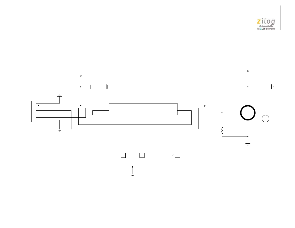
Figures 4 and 5 show schematics for the ZMOTION Detection Module II and the ZDM II Evaluation Board, respectively.
Figure 4. Schematic Diagram of the ZMOTION Detection Module II
-SLP / -DBG
LG
-MD / -RST
RXD / DLY
TXD / SNS
VCC
VCC
VCC
U2
ZRE200B
D
1
S
2
GN
D
3
LS1
ZNCL-10IL
J1
1x8 RT-ANGL
1
2
3
4
5
6
7
8
R1
47K
C2
1μF
J2
1
C1
1μF
J3
1
J4
1
U1
Z8FS040BSB20EG
PA2/RESET/DE0/T1OUT
4
PA1/T0OUT/XOUT/ANA3/VREF/CLKIN
3
PA0/T0IN/T0OUT/XIN/DBG
2
PA5/TXD0/T1OUT/ANA0/CINP
7
PA4/RXD0/ANA1/CINN
6
ANA2
5
VSS
8
VDD
1
Advertising
This manual is related to the following products: