Power and data connections – Zytronic ZXY110 User Manual
Page 22
Advertising
Integration Manual - Issue 1
Zytronic Projected Capacitive ZXY100/110
®
Touch Controller & Sensor
22
POWER AND DATA CONNECTIONS
A USB cable should be connected to the mini-B socket on the controller PCB (or Serial cable for Serial
type controllers), as shown in Figure 20.
USB CABLE PLUGGED INTO CONTROLLER PCB
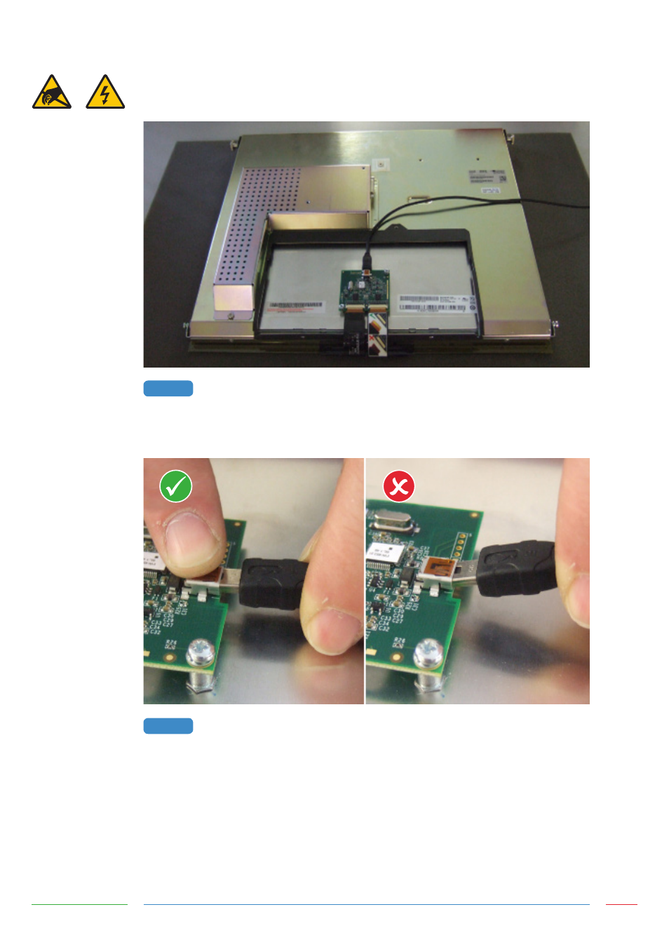
Care should be taken when inserting the USB connector into the socket to avoid damage or lifting of
the USB connector from the PCB, as shown in Figure 21.
CORRECT AND INCORRECT USB CABLE INSERTION INTO USB MINI-B SOCKET
The USB cable should be fixed to the chassis near to the controller PCB, as shown in Figure 22.
FIGURE 20
FIGURE 21
Advertising
This manual is related to the following products: