3 leds, 4 connectors, 3 leds 3.4 connectors – Artesyn COMX-CAR-210 Installation and Use (August 2014) User Manual
Page 30: Table 3-2, Led function description, Controls, leds, and connectors
Controls, LEDs, and Connectors
COMX-CAR-210 Installation and Use (6806800L14D)
30
3.3
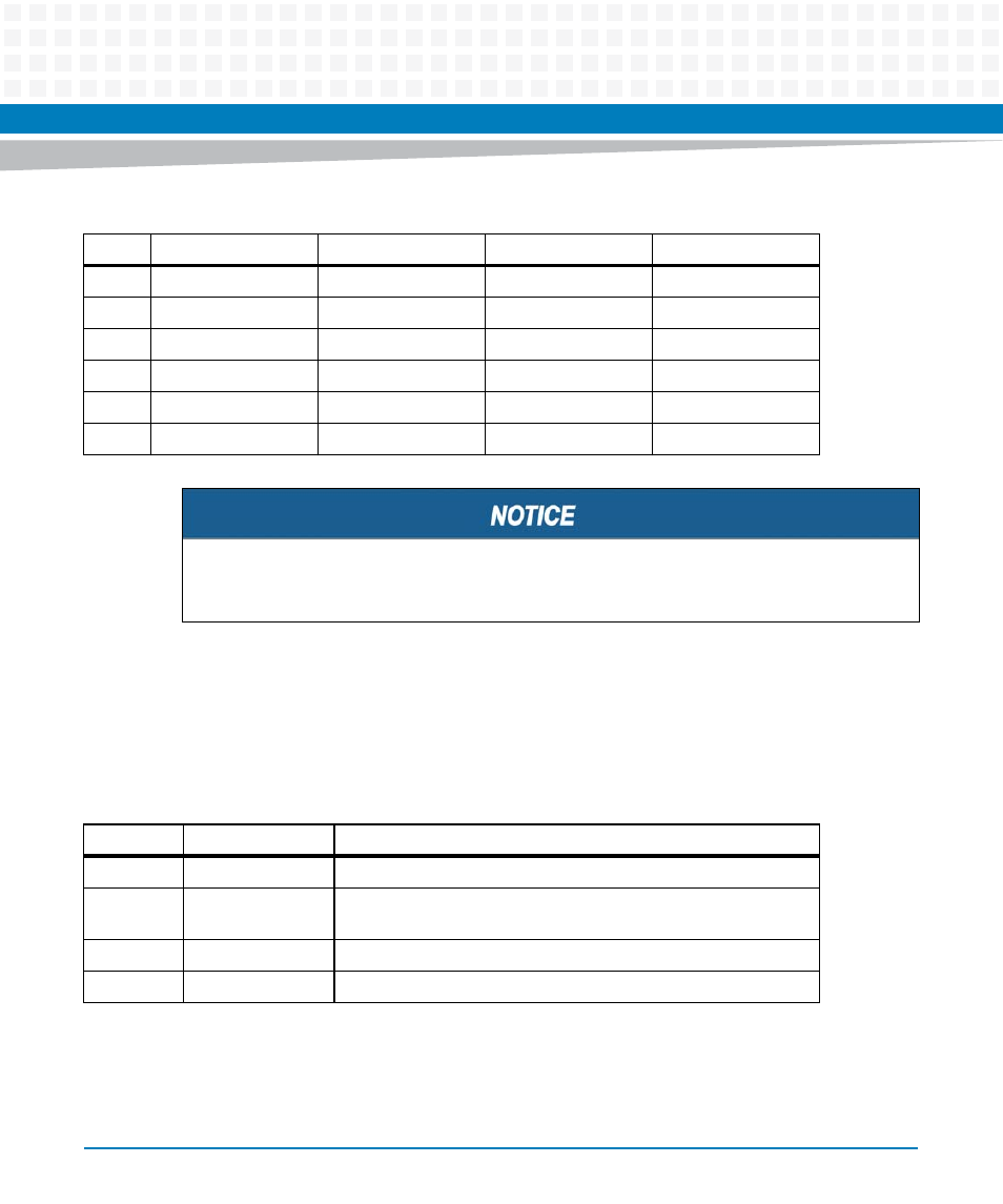
LEDs
The COMX-CAR-210 implemented some LEDs to indicate system status. The detailed function
description is listed below.
3.4
Connectors
This section lists down the information on the connectors of the COMX-CAR-210.
105
VCC_12V
VCC_12V
VCC_12V
VCC_12V
106
VCC_12V
VCC_12V
VCC_12V
VCC_12V
107
VCC_12V
VCC_12V
VCC_12V
VCC_12V
108
VCC_12V
VCC_12V
VCC_12V
VCC_12V
109
VCC_12V
VCC_12V
VCC_12V
VCC_12V
110
GND (FIXED)
GND (FIXED)
GND (FIXED)
GND (FIXED)
The signals group of PEG_TX [0:3] and PEG_RX [0:2] are routed to two PCIE Mux to switch
the signals between PEG and SDVO.
Table 3-1 COM EXPRESS Connector Pin Definition (continued)
Row
A
B
C
D
Table 3-2 LED function description
Location
Status
Description
D34
Type 2 Error
ON: Module does not comply with Type 2 spec
D26
Thermal Trip
ON: CPU is hot, system will shut down (only when the system is
running)
D21
Platform reset
ON: All power is OK and system is ready to start
D28
Suspend
ON: The module status is suspended