6 spi flash, Table 3-41, P47, sf100 header pin-out – Artesyn COMX-CAR-210 Installation and Use (August 2014) User Manual
Page 50: Table 3-42, P46, spi flash configuration, Table 3-43, P12, bios configuration on the module, Table 3-44, P43, bios configuration on the module, Controls, leds, and connectors
Advertising
Controls, LEDs, and Connectors
COMX-CAR-210 Installation and Use (6806800L14D)
50
3.5.6
SPI Flash
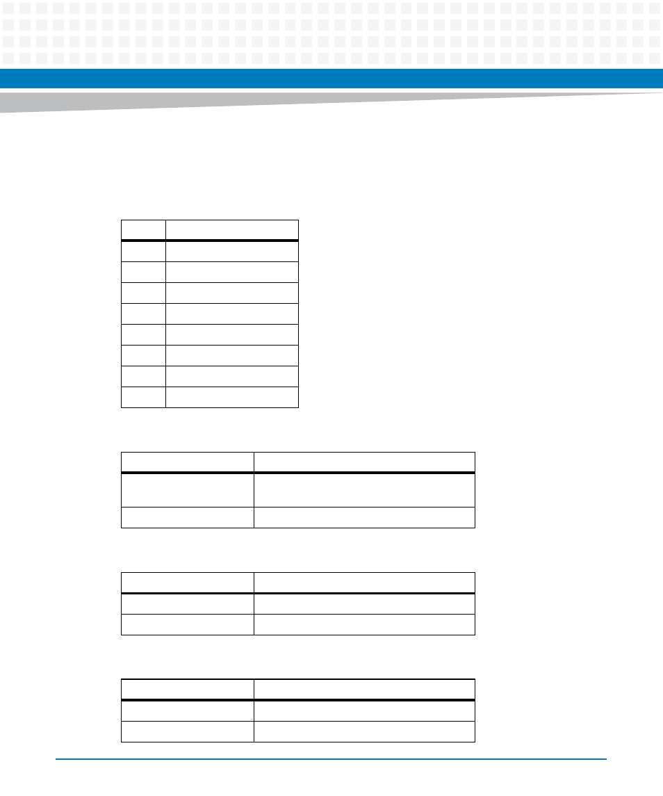
Table 3-41 P47, SF100 Header Pin-out
Pin
Signal
1
3.3V
2
GND
3
SPI_CS_N
4
SF_SPI_CLK
5
SF_SPI_SO
6
SF_SPI_SI
7
NC
8
NC
Table 3-42 P46, SPI Flash Configuration
Jumper setting
Configuration
P46 (1-2)
Enable SPI flash chip U9 and disable U10
(Default)
P46 (2-3 )
Enable SPI flash chip U10 and disable U9
Table 3-43 P12, BIOS Configuration on the module
Jumper setting
Configuration
P12 (1-2)
Enable CS0 of BIOS on the Module (Default)
P12 (2-3)
Disable CS0 of BIOS on the Module
Table 3-44 P43, BIOS Configuration on the module
Jumper setting
Configuration
P43 (1-2)
Enable CS1 of BIOS on the Module (Default)
P43 (2-3)
Disable CS1 of BIOS on the Module
Advertising