Table 3-5, P7, lvds power supply jumper configuration, Table 3-6 – Artesyn COMX-CAR-210 Installation and Use (August 2014) User Manual
Page 32: P35, lvds power supply jumper configuration, Controls, leds, and connectors
Controls, LEDs, and Connectors
COMX-CAR-210 Installation and Use (6806800L14D)
32
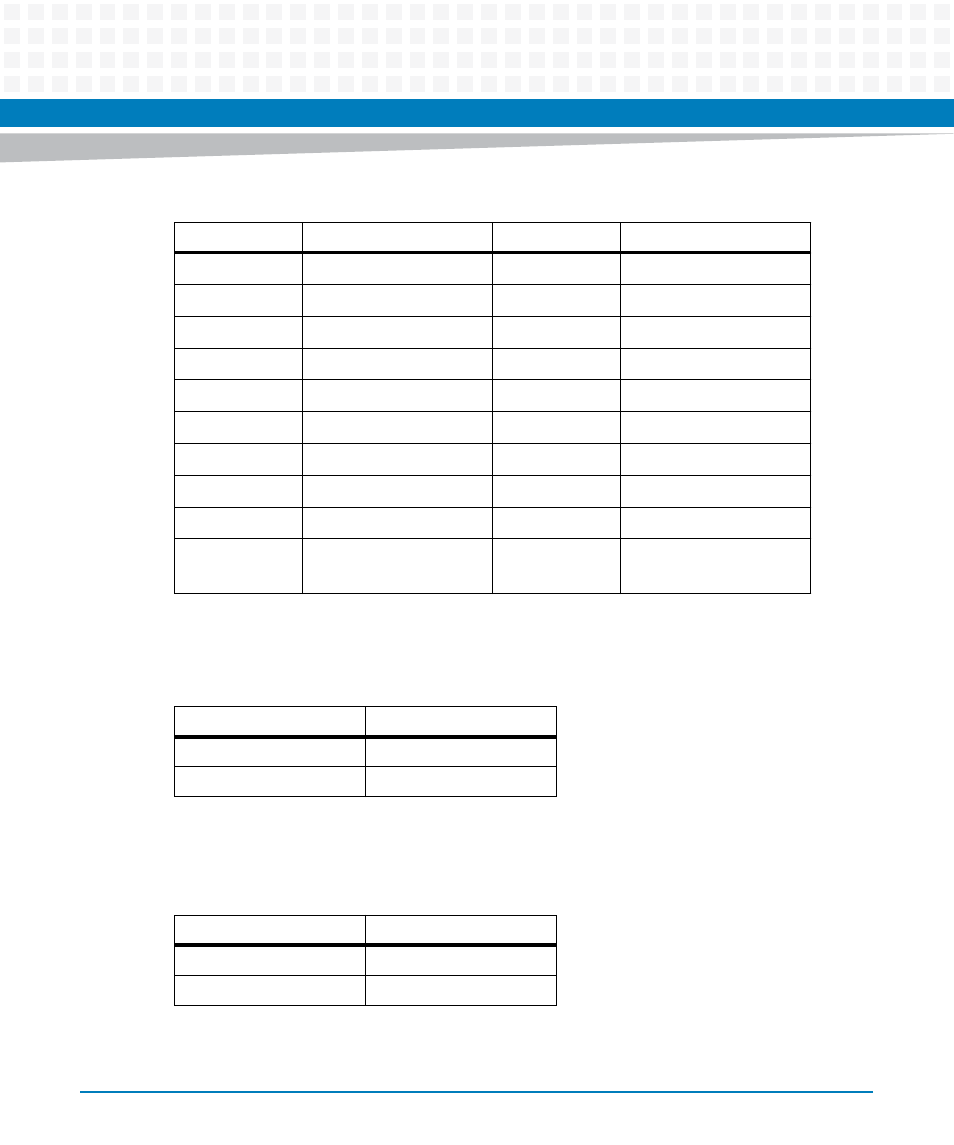
The 3V or 5V DC for the LVDS power supply is configured through the 3-pin jumper P7.
The 12V DC LVDS power supply is configured through the 3-pin header P35.
9
LVDSA_DATA1_N
10
LVDSB_DATA1_N
13
LVDSA_DATA2_P
14
LVDSB_DATA2_P
15
LVDSA_DATA2_N
16
LVDSB_DATA2_N
19
LVDSA_DATA3_P
20
LVDSB_DATA3_P
21
LVDSA_DATA3_N
22
LVDSB_DATA3_N
25
LVDSA_CLK_P
26
LVDSB_CLK_P
27
LVDSA_CLK_N
28
LVDSB_CLK_N
31
LVDS_I2C_CLK
32
LVDS_I2C_DATA
33,35,37,39
VDD (3.3V OR 5V)
36,38,40
VDD (12V)
5,
11,17,23,29
GND
6,12,18,24,30
,34
GND
Table 3-5 P7, LVDS Power Supply Jumper Configuration
Jumper Setting
Configuration
P7 (1-2)
3.3 V (Default)
P7 (2-3)
5V
Table 3-6 P35, LVDS Power Supply Jumper Configuration
Jumper Setting
Configuration
P35 (1-2)
Enable 12V
P35 (2-3)
NC (Default)
Table 3-4 P6, LVDS Connector Pin Definition (continued)
Pin
Signal
Pin
Signal