9 gpio, Table 7-3, Gpio states – Artesyn COMX-P4080 Installation and Use (August 2014) User Manual
Page 94: Bsp operations
BSP Operations
COMX-P4080 COM Express Module Installation and Use (6806800L20C)
94
When the U-Boot detects the DDR3 SDRAM during boot up, the following message appears:
7.9
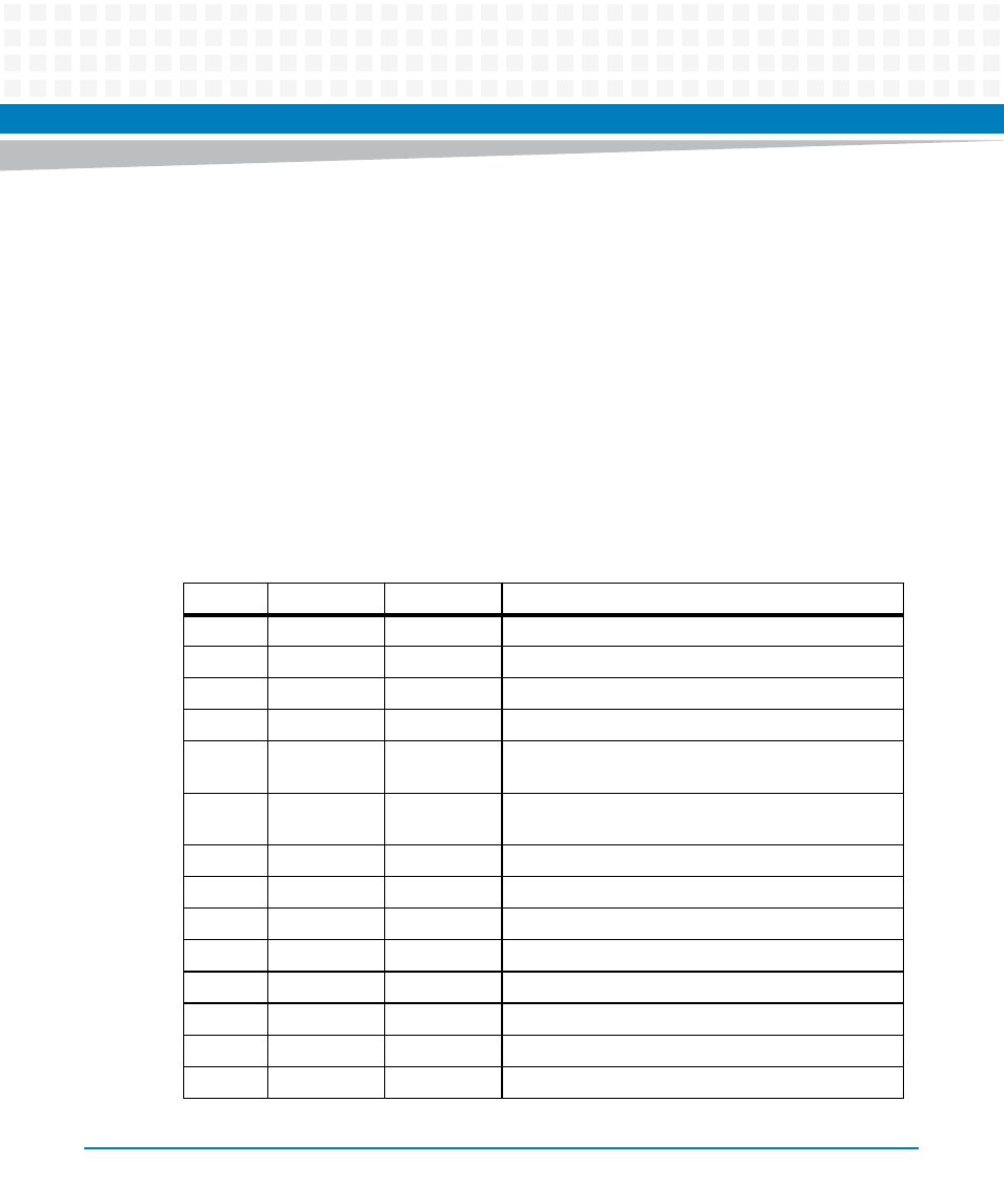
GPIO
COMX-P4080 has fourteen general purpose input/output (GPIO).
DRAM: Initializing...
2 GB left unmapped
DDR: 4 GB (DDR3, 64-bit, CL=9, ECC on)
DDR Controller Interleving Mode: cache line
DDR Chip-Select Interleaving Mode: CS0+CS1
Table 7-3 GPIO States
GPIO#
Input/Output
Reset State
Description
GPIO00
I
I
GPI0 of COM-E connectors
GPIO01
I
I
GPI1 of COM-E connectors
GPIO02
I
I
GPI3 of COM-E connectors
GPIO03
I
I
GPI4 of COM-E connectors
GPIO04
O
I
GPO0 of COM-E connectors and also as to control
debug LED D18
GPIO05
O
I
GPO1 of COM-E connectors and also as to control
debug LED D19
GPIO06
O
I
GPO3 of COM-E connectors
GPIO07
O
I
GPO4 of COM-E connectors
GPIO18
O
I
Watchdog Input
GPIO19
O
I
Clock Generator Enable
GPIO20
O
I
Carried board reset output
GPIO23
I
I
Clock generator of bank 1 frequency selection input
GPIO24
I
I
Clock generator of bank 2 frequency selection input
GPIO26
I
I
Clock generator of bank 3 frequency selection input