4 backplane connectors, 1 rp0 connector, Table 3-1 – Artesyn iVPX7225 RTM Installation and Use (April 2015) User Manual
Page 35: Rp0 connector pinout, Controls, leds and connectors
Controls, LEDs and Connectors
iVPX7225 RTM Installation and Use (6806800S35B)
35
3.4
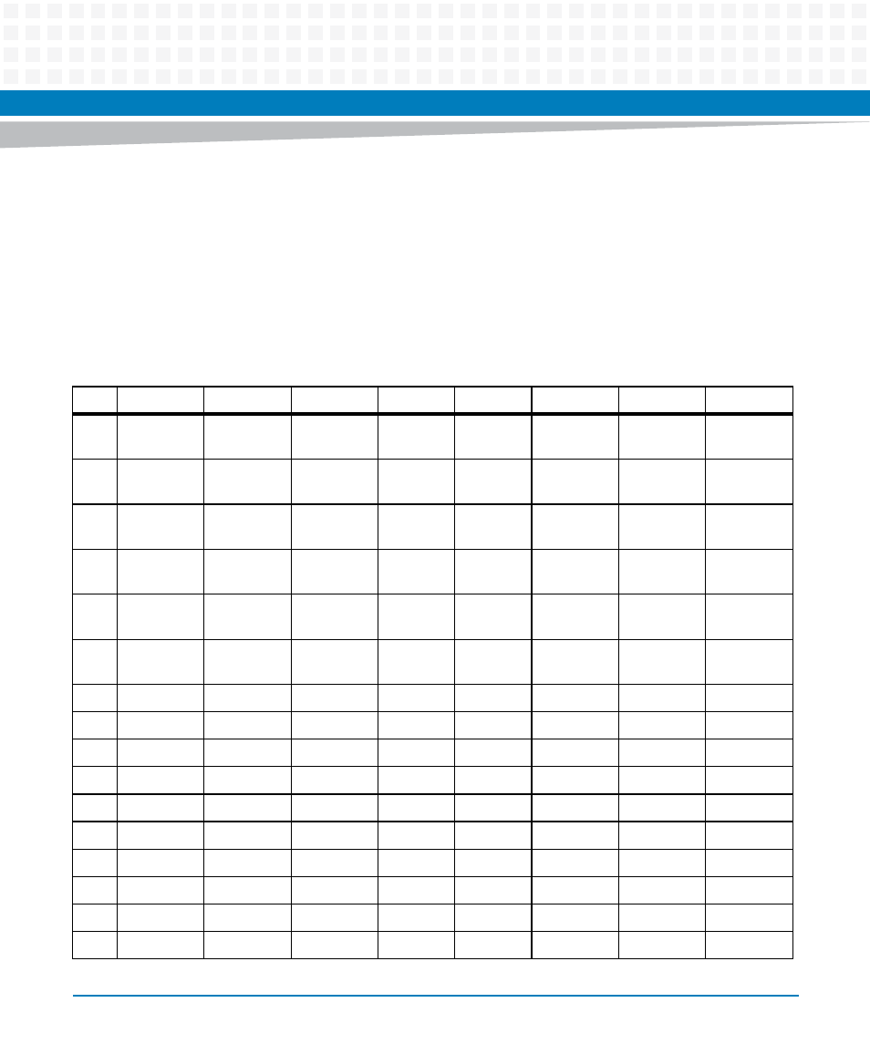
Backplane Connectors
The board provides the RP0, RP1 and RP2 backplane connectors.
3.4.1
RP0 Connector
The following table provides the pinout of the RP0 connector.
Table 3-1 RP0 Connector Pinout
Pin
Wafer Type
Row G
Row F
Row E
Row D
Row C
Row B
Row A
1
Power
(VOID)
NC
NC
NC
NC
3.3V VPX
PWR
3.3V VPX
PWR
3.3V VPX
PWR
2
Power
NC
NC
NC
NC
3.3V VPX
PWR
3.3V VPX
PWR
3.3V VPX
PWR
3
Power
5.0 VPX
PWR
5.0 VPX
PWR
5.0 VPX
PWR
NC
5.0 VPX
PWR
5.0 VPX
PWR
5.0 VPX
PWR
4
Single
Ended
NC
NC
GND
NC
GND
NC
NVMRO
5
Single
Ended
NC
NC
GND 3.3V
AUX
VPX
GND NC
NC
6
Single
Ended
NC
NC
GND NC
GND NC
NC
7
Differential
NC
GND NC
NC
GND NC
NC
8
Differential GND
NC
NC
GND
NC
NC
GND
9
Differential NC
GND
NC
NC
GND
NC
NC
10
Differential GND
NC
NC
GND
NC
NC
GND
11
Differential VBAT
1
GND
NC
NC
GND
NC
NC
12
Differential GND
NC
NC
GND
NC
NC
GND
13
Differential NC
GND
NC
NC
GND
NC
NC
14
Differential GND
NC
NC
GND
NC
NC
GND
15
Differential NC
GND
NC
NC
GND
NC
NC
16
Differential GND
NC
NC
GND
NC
NC
GND