1 smt configuration switch, s1, Figure 2-4, Smt configuration switch position – Artesyn MVME4100 Single Board Computer Installation and Use (June 2014) User Manual
Page 35
Hardware Preparation and Installation
MVME4100 Single Board Computer Installation and Use (6806800H18G)
35
The following sections describe the on-board switches and their configurations for the
MVME4100.
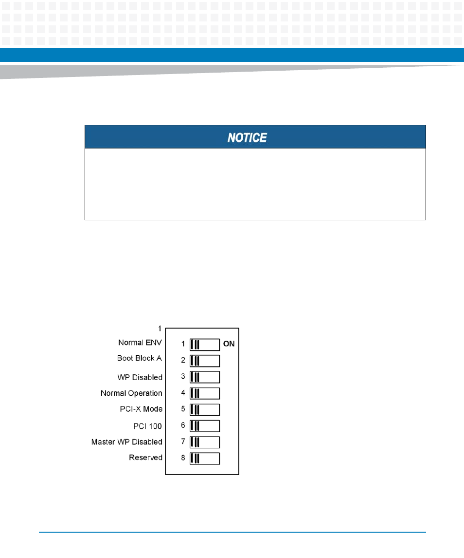
2.4.1
SMT Configuration Switch, S1
An 8-position SMT configuration switch is located on the MVME4100 to control the flash bank
write-protect, select the flash boot image, and control the safe start ENV settings. The default
setting on all switch positions is OFF and is indicated by brackets in
.
Board Malfunction
Switches marked as "reserved" might carry production-related functions and can cause the
board to malfunction if their setting is changed.
Do not change settings of switches marked as "reserved". The setting of switches which are
not marked as "reserved" has to be checked and changed before board installation.
Figure 2-4
SMT Configuration Switch Position