4 seeprom address switch, s1, Table 5-2, Seeprom address switch assignments (rtm) – Artesyn MVME4100 Single Board Computer Installation and Use (June 2014) User Manual
Page 84: Table 5-3, Switch settings and device addresses, Figure 5-3, S1 switch positions, Seeprom address, Switch, s1, Transition module
Transition Module
MVME4100 Single Board Computer Installation and Use (6806800H18G)
84
5.4
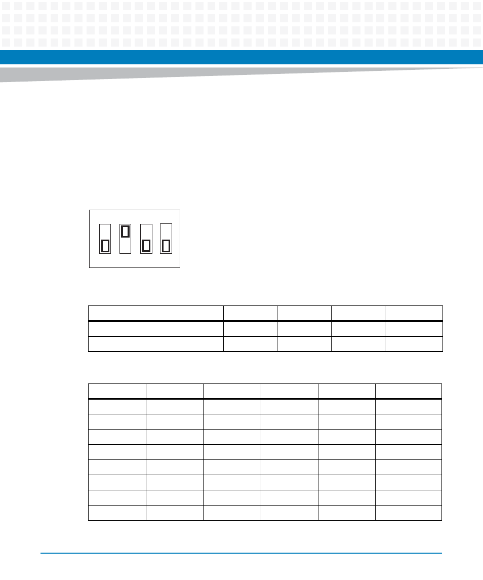
SEEPROM Address Switch, S1
A 4-position SMT configuration switch is located on the MVME7216E transition module to set
the device address of the RTM serial EEPROM device and to control its write protection (if SW4
is OFF, write is enabled). The switch settings are defined in the next table. To see the switch
location, refer to
.
Figure 5-3
S1 Switch Positions
Table 5-2 SEEPROM Address Switch Assignments (RTM)
Position
SW4
SW3
SW2
SW1
Function
WP
A(2)
A(1)
A(0)
Default (OFF)
0
1
1
1
Table 5-3 Switch Settings and Device Addresses
SW4
SW3
SW2
SW1
A(2:0)
Device Address
OFF
ON
ON
ON
000
$A0
OFF
ON
ON
OFF
001
$A2
OFF
ON
OFF
ON
010
$A4
OFF
ON
OFF
OFF
011
$A6
OFF
OFF
ON
ON
100
$A8
OFF
OFF
ON
OFF
101
$AA (default)
OFF
OFF
OFF
ON
110
$AC
OFF
OFF
OFF
OFF
111
$AE
ON
1
2
3
4