Table 5-7, Ethernet connectors pin assignment, Table 5-8 – Artesyn MVME4100 Single Board Computer Installation and Use (June 2014) User Manual
Page 89: Com port connector pin assignments, Transition module, Ethernet connectors (gige/j41b, gige/j2b,gige/j2a)
Transition Module
MVME4100 Single Board Computer Installation and Use (6806800H18G)
89
5.5.2
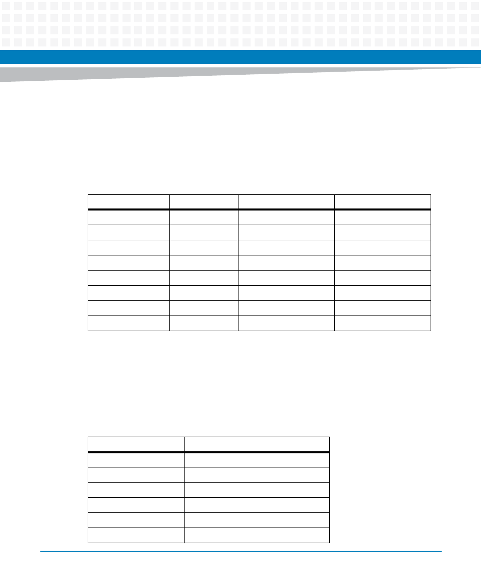
Ethernet Connectors (GIGE/J41B, GIGE/J2B,GIGE/J2A)
The MVME4100 routes two 10/100/1000Mb/s full duplex Ethernet interfaces to the VMEbus
P2 connector. The MVME7216E routes these from the P2 connector to the RJ-45 connectors on
RTM panel. These connectors include integrated LEDs for speed and activity indication. The pin
assignments for these connectors are as follows:
5.5.3
Serial Port Connectors (COM1/J41A, COM2–COM5/J2A-D)
The MVME4100 routes four asynchronous serial port interfaces, SP1 – SP4, to the VMEbus P2
connector. The MVME7216E routes these from the P2 connector to the RJ-45 connectors on
RTM panel. The pin assignments for these connectors are as follows:
Table 5-7 Ethernet Connectors Pin Assignment
Pin #
Signal
1000 Mb/s
10/100 Mb/s
1
MDIO0+
_DA+
TD+
2
MDIO0-
_DA-
TD-
3
MDIO1+
_DB+
RD+
4
MDIO1-
_DC+
Not Used
5
MDIO2+
_DC-
Not Used
6
MDIO2-
_DB-
RD-
7
MDIO3+
_DD+
Not Used
8
MDIO3-
_DD-
Not Used
Table 5-8 COM Port Connector Pin Assignments
Pin
Signal
1
No connect
2
RTS
3
GND
4
TX
5
RX
6
GND