Table 2-4, Thermally significant components, Wn in – Artesyn MVME7100ET Single Board Computer Installation and Use (June 2014) User Manual
Page 30: Figure 2-1, Figure 2-2, Hardware preparation and installation
Hardware Preparation and Installation
MVME7100ET Single Board Computer Installation and Use (6806800K87E)
30
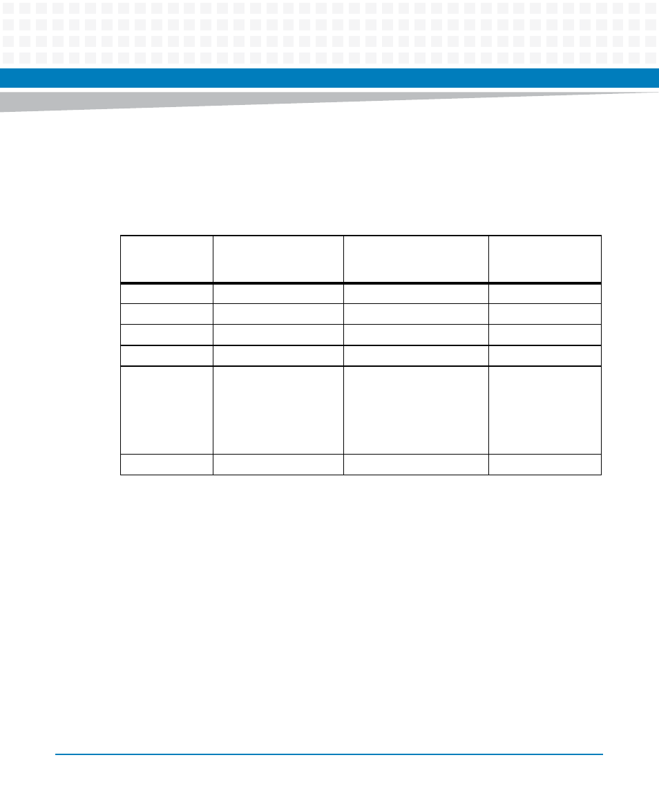
The preferred measurement location for a component may be junction, case, or ambient as
specified in the table below. Junction temperature refers to the temperature measured by an
on-chip thermal device. Case temperature refers to the temperature at the top, center surface
of the component. Air temperature refers to the ambient temperature near the component.
Table 2-4 Thermally Significant Components
Reference
Designator
Generic Description
Maximum Allowable
Component Temperature in
Centigrade
Measurement
Location
U27, U4
Gb Ethernet Transceiver
105°
Ambient
U25, U26, U28
PCI-X/PCI-Express Bridge
85°
Junction
U22
PCI-Express Bridge
115°
Ambient
U24
VME Bridge
90°
Junction
U10, U11, U12,
U13, U14, U56,
U57, U58, U59,
U6, U60, U61,
U62, U63, U64,
U7, U8, U9
DDR2 SDRAM
95°
Case
U20
MPU
105°
Junction