2 usb connector, Figure 3-8, Ethernet interface connectors pinout – Artesyn RTM-ATCA-7360 Installation and Use (June 2014) User Manual
Page 57: Figure 3-9, Location of usb connectors, Figure 3-10, Usb connector pinout, Controls, leds, and connectors, The pinout of the connector is as follows
Advertising
Controls, LEDs, and Connectors
RTM-ATCA-7360 Installation and Use (6806800J08M)
57
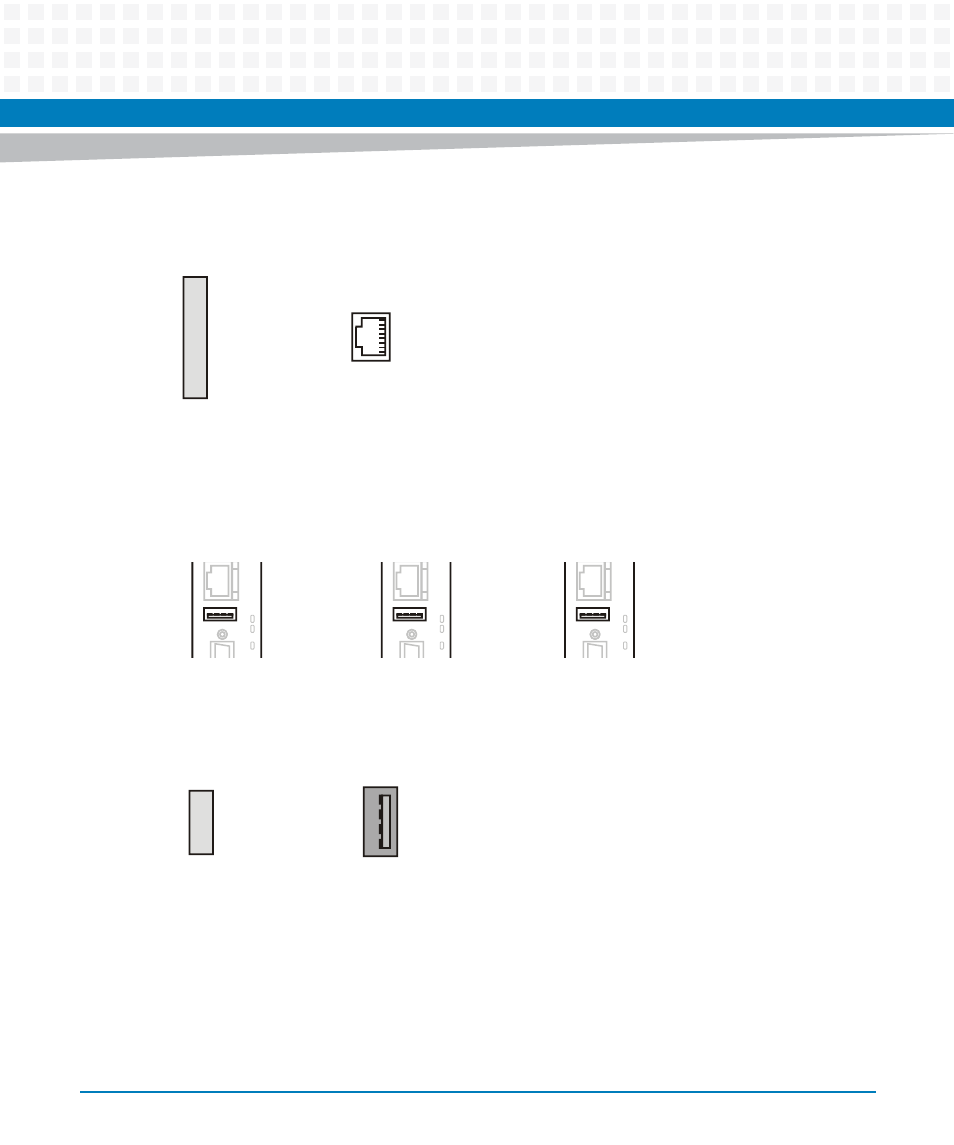
The pinout of the connector is as follows.
3.2.3.2
USB Connector
The RTM provides one USB connector at its face plate. It is compliant to the USB 2.0 standard.
The pinout of each USB connector is given in the following.
Figure 3-8
Ethernet Interface Connectors Pinout
1
8
1
2
3
4
5
6
7
8
ETH_TX+
ETH_TX-
ETH_RX+
n.c.
n.c.
ETH_RX-
n.c.
n.c.
Figure 3-9
Location of USB Connectors
Figure 3-10 USB Connector Pinout
H
R
N
E
T
U
S
B
S
0
1
SAS port
activity LEDs
H
R
N
E
T
U
S
B
S
0
1
SAS port
activity LEDs
H
R
N
E
T
U
S
B
S
0
1
SAS port
activity LEDs
1
2
3
4
1
4
VP5_USB
USB_x_D-
USB_x_D+
GND
Advertising
This manual is related to the following products: