3 sas connector, Figure 3-11, Location of sas connector – Artesyn RTM-ATCA-7360 Installation and Use (June 2014) User Manual
Page 58: Figure 3-12, Sas connector pinout, Controls, leds, and connectors, Sas port activity leds
Advertising
Controls, LEDs, and Connectors
RTM-ATCA-7360 Installation and Use (6806800J08M)
58
3.2.3.3
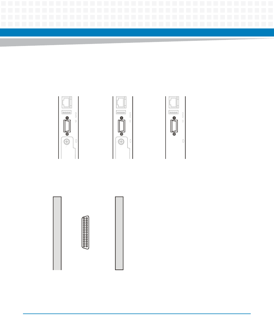
SAS Connector
The blade provides one SAS connector at its face plate. The location of the connector is shown
in the following figure.
The pinout of the serial interface connector is shown below.
Figure 3-11 Location of SAS Connector
Figure 3-12 SAS Connector Pinout
H
/
S
H
D
D
E
R
N
E
T
U
S
B
S
A
S
0
1
SAS port
activity LEDs
H
/
S
H
D
D
E
R
N
E
T
U
S
B
S
A
S
0
1
SAS port
activity LEDs
H
/
S
H
D
D
E
R
N
E
T
U
S
B
S
A
S
0
1
SAS port
activity LEDs
G1
S2
G2
S4
G3
S6
G4
S8
G5
S10
G6
S12
G7
S14
G8
S16
G9
G1
S1
G2
S3
G3
S5
G4
S7
G5
S9
G6
S11
G7
S13
G8
S15
G9
GND
Rx 0-
GND
Rx 1-
GND
RSVD
GND
RSVD
GND
RSVD
GND
RSVD
GND
Tx 1+
GND
Tx 0+
GND
GND
Rx 0+
GND
Rx 1+
GND
RSVD
GND
RSVD
GND
RSVD
GND
RSVD
GND
Tx 1-
GND
Tx 0-
GND
Advertising
This manual is related to the following products: