2 gpio, Table 5-2, Gpio description – Artesyn COMX-P2020 BSP User Guide (July 2014) User Manual
Page 49: U-boot deployment
U-boot Deployment
COMX-P2020 BSP User Guide (6806800L84B)
49
5.4.2
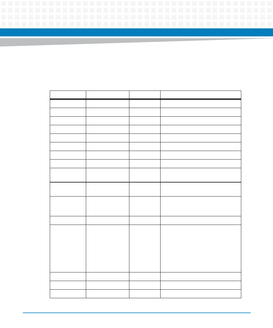
GPIO
There are a total of 16 GPIO used at COMX-P2020.
Table 5-2 GPIO Description
Name
Intput/ Output
Reset Value
Description
GPIO 0
Input
Connected to the COM-E Carrier Board
GPIO 1
Input
Connected to the COM-E Carrier Board
GPIO 2
Input
Connected to the COM-E Carrier Board
GPIO 3
Input
Connected to the COM-E Carrier Board
GPIO 4
Output
0
Connected to the COM-E Carrier Board
GPIO 5
Output
0
Connected to the COM-E Carrier Board
GPIO 6
Output
0
Connected to the COM-E Carrier Board
GPIO 7
Output
0
Connected to the COM-E Carrier Board
GPIO 8
Multiplex as SDHC_CD: which is used to
check if the SD insert or not.
GPIO 9
Multiplex as SDHC_WP: which is used
to check the SD is write protect or not.
GPIO 10
Output
0
It can be used to clear WDT timer.
If the pin is set to 1, the WDT timer will
be cleared.
GPIO 11
Input
Connect to COM-E Carry board
GPIO 12
Output
1
If this pin is set to 1, and s3[14] is set to
OFF, then Serdes#2 is switch to COMe
PCI #2;
If this pin is set to 0, or s3[14] is set to
ON, then Serdes#2 is switch to GEPHY2.
For Blackadder-P2020, GPIO[12] must
be set to 1 and s3[14] must be set to
OFF.
GPIO 13
Input
Connect to COM-E Carry board.
GPIO 14
Output
Connect to COM-E Carry board
GPIO 15
Input
Connect to COM-E Carry board