Thermostat, Ptional, Quipment – Avalon Firestyles DVS Fireplace-1997 to 2000 User Manual
Page 43: Ontinued
O
PTIONAL
E
QUIPMENT
(C
ONTINUED
)
P
AGE
43
Thermostat
(Part # 99300650)
!
Do not connect 120 VAC to the gas control valve or wiring of this unit.
+
It is easiest to route the wire prior to installing the fireplace. Route the wire to a location near the gas
inlet. Allow 3' of wire for hookup inside the fireplace.
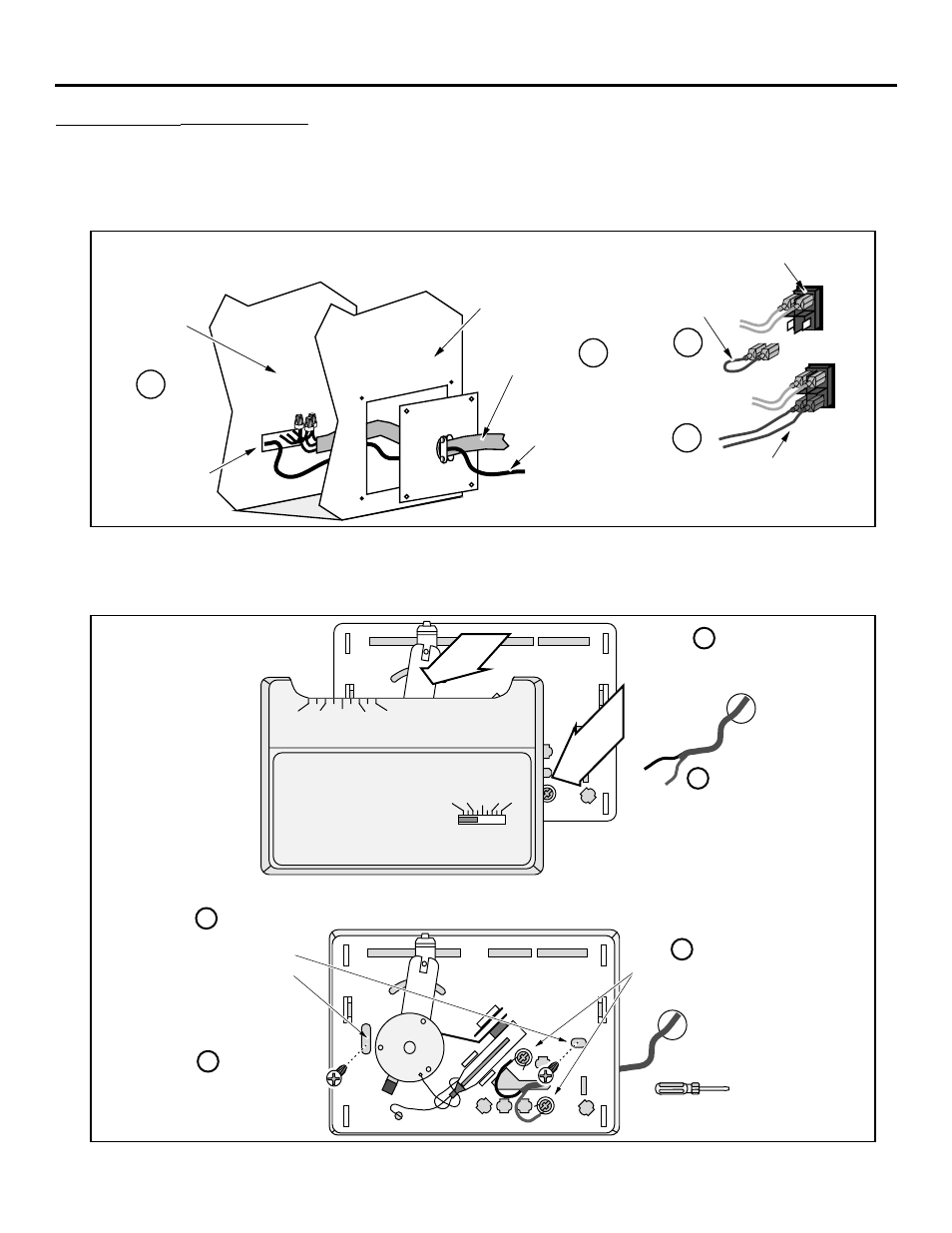
1
Follow the directions below to attach the wire to the on/off switch (NOTE: this is best done at the
same time the electrical line is hooked up - see page 23 for details on installing the electrical line).
Run the wire through
the strain relief next
to the electrical line.
Then thread the wire
through the square
opening (this leads to
the area below the
burner pan).
Electrical
LIne
Outer Wall of Z.C. Can.
Inner Wall
of Z.C.
Can.
Insert
approximately
1' (305 mm) of
wire through
the inner wall
to allow for
hookup.
Right Side of Fireplace
a
Back of on/off switch
Remove the green
jumper wire.
c
Attach the quick connects
from the wire to the two
posts on the on/off switch.
d
b
2
Determine a location for the thermostat that is within range of the 50' length of thermostat wire. It
should be centralized in the room and away from the heater. The wire may be routed externally on
the wall or behind the wall (preferred).
3
Install the thermostat following the directions below.
50 60 70 80 90
50 60 70 80 90
Robertshaw
Run the thermostat wires
through the wall (cut off excess
wire, leaving 6Ó of slack).
Pull the cover off the thermostat
Expose 1/2Ó of wire and
attach to these two posts.
Standard
Screwdriver
Attach the thermostat to
the wall through these
two holes.
a
b
c
d
Re-attach the cover
removed in step ÒaÓ.
e