Pin assignment of the connector – BECKHOFF C6920 User Manual
Page 16
Installation Instructions
signal lamp connection or via a contactor. With this solution the main
switch generally only has to be switched off if the control cabinet has to be
opened. The battery will only be used in the event of a power failure.
In order to maintain a screen display for the Industrial PC in the event of a
power failure, the power supply unit is equipped with a UPS output 27 V /
1.4 A for connecting a Control Panel with a display dimension up to 19
inches. This enables a power failure to be visualized and displayed to the
user. Once the PC has shut down, the UPS output is switched off.
For a detailed functional description please refer to section
Connecting
Power Supply
.
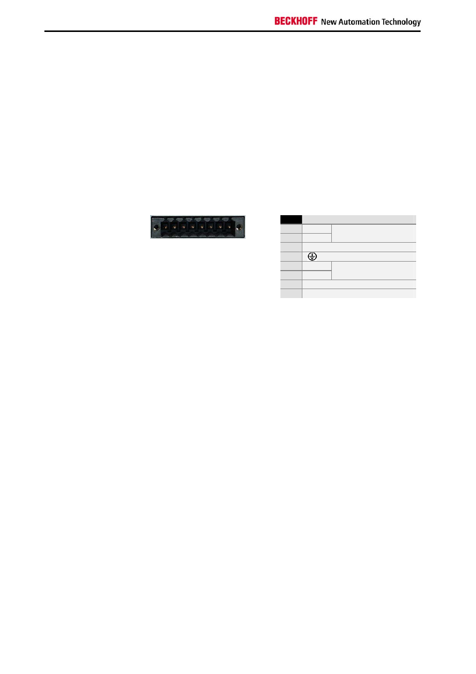
Pin assignment of the connector
The power supply and the external circuit for switching the Industrial PC on
and off are connected via the 8-pole plug connector .
Pin assignment for
connecting the switch, the
power supply and the
battery pack (optional)
Pin
Function
1
-
2
+
Battery Pack
(with UPS only)
3
UPS+ (Output)
4
5
-
6
+
24 V DC
Power Supply
7
PC_ON
8
Power-Status
1 2 3 4 5 6 7 8
14
C6920/ 25