Terminal configuration – BECKHOFF KL5051 User Manual
Page 7
Terminal configuration
KL5051
7
Terminal configuration
The terminal can be configured and parametrized via the internal register
structure.
Each terminal channel is mapped in the bus coupler. The data of the termi-
nal is mapped differently in the memory of the bus coupler depending on
the type of the bus coupler and on the set mapping configuration (eg Moto-
rola/ intel format, word alignment,...). For parametrization of a terminal, the
control/status byte must als be mapped.
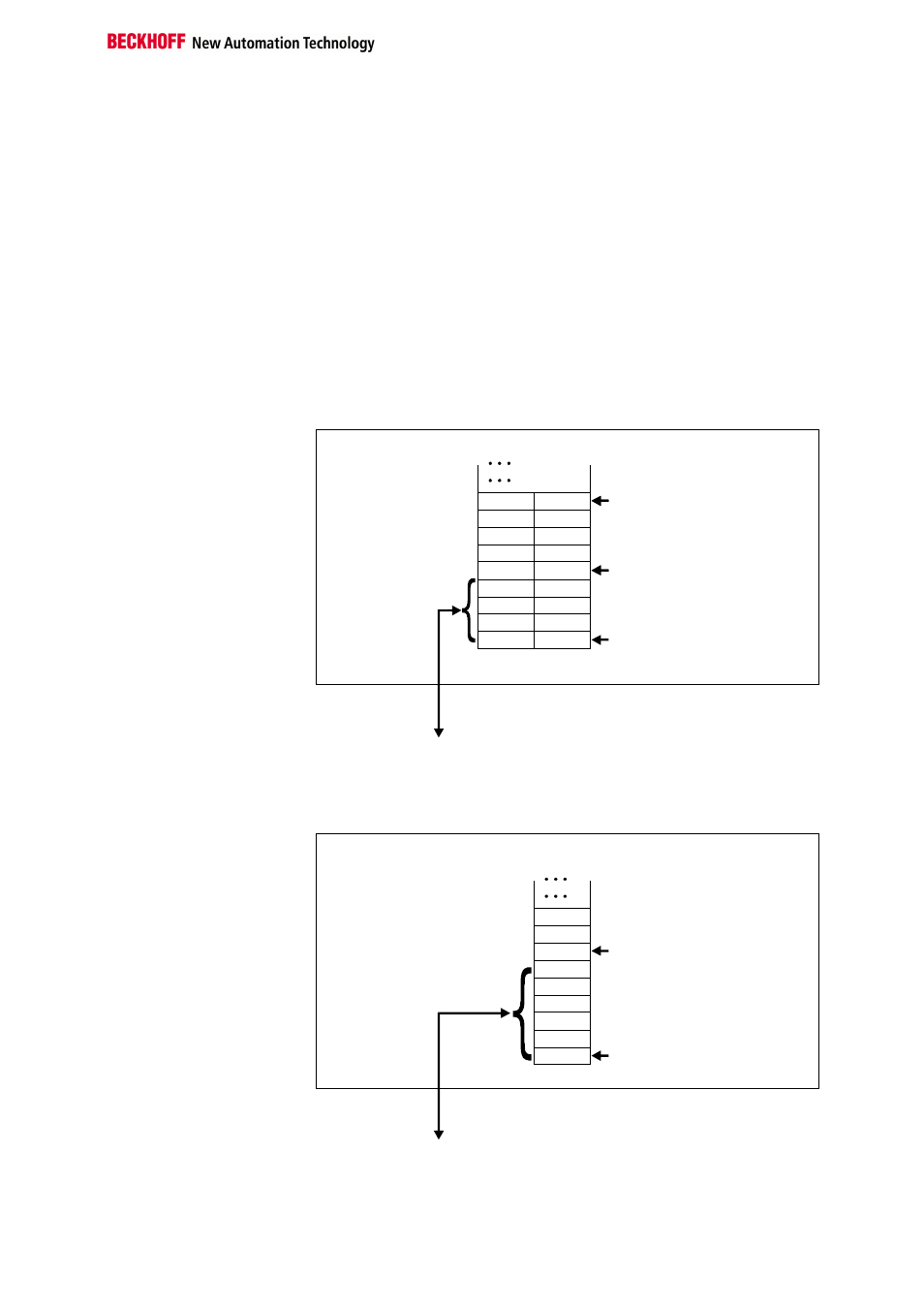
Beckhoff Lightbus
coupler BK2000
In the case of the Beckhoff Lightbus coupler BK2000, the control /status
byte is also always (ie in the case of all analog terminals) mapped in addi-
tion to the data bytes. It is always in the low byte at the offset address of
the terminal channel.
0
Offset Terminal1 Channel1 = 0
Offset Terminal2 Channel1 = 4
KL5051
Offset Terminal2 Channel2 = 8
User data allocation depending
on mapping.
K-Bus
Beckhoff-Lightbus
bus coupler
BK2000
To the bus terminal
L
H
C/S-0
C/S-3
D1
D4
Data L
Data H
Data H
Data L
-
-
D2
D5
C/S
C/S
C/S
The terminal is
mapped in the
bus coupler.
Profibus coupler BK3000
In the case of the Profibus coupler BK3000, the KL5051 is always mapped
with 6 bytes of input and 6 bytes of output data.
Offset Terminal1 Channel1 = 0
KL5051
Offset Terminal2 Channel1 = 6
The control/status byte
must be inserted for
parameterization .
K-Bus
Profibus bus coupler
BK3000
To the bus terminal
D5
D4
D1
D2
Data H
Data L
Data L
C/S-0
C/S-3
0
The terminal is
mapped in the
bus coupler