2 functional description – BECKHOFF KL5101-0000 User Manual
Page 6
Product overview
4
KL5101
2.2 Functional description
The incremental encoder interface terminal KL5101 enables the connection
of any incremental encoders to the bus coupler or the PLC. A 16-bit
counter with a quadrature decoder and a 16-bit latch can be read, set or
activated. Besides the decoder inputs A, B, C, an additional latch input G1
(24 V) and a gate input G2 (24 V) for disabling the counter are available.
The 16-bit up / down counter mode can also be selected. In this mode of
operation, input B is the counting input.
1-fold, 2-fold or 4-fold evaluation of the encoder signals A, B, C in simple or
complementary form can be parameterized via the field bus.
The terminal is supplied as a 4-fold quadrature decoder with
complementary evaluation of the encoder signals A, B, C. For operation of
the encoder interface, the operating voltage of 24 V DC must be connected
to the terminal contacts in addition to the encoder inputs.
Starting from hardware state 03 (beginning from 6.18.98) the KL5101 has
new, additional features:
Incremental encoder with fault alarm outputs can be connected to the
Status input of the KL5101.
A period measurement with a resolution of 200 ns can also be performed.
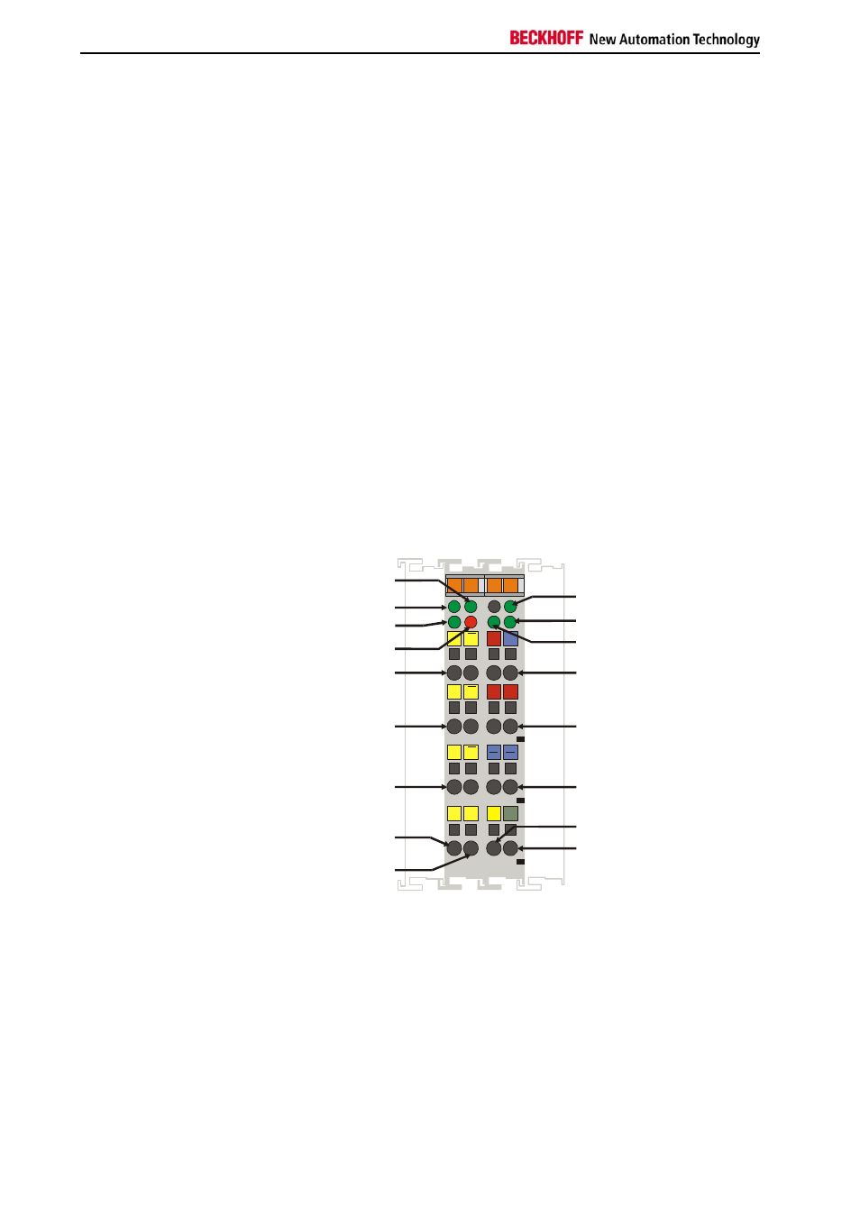
Assignments of
terminal contacts
LED-input C
Run-LED
LED-input A
Latch-LED
LED-input B
Gate-LED
LED Status input
Input A, /A
Ue, Uo
Input B, /B
+ 24 V (2x)
Input C, /C
0 V (2x)
ext. Latch 24 V
ext. Gate 24 V
Shield (1x)
Status input
13
15
Ue
B
A
C
B
A
C
+
+
S
14
16
Uo
G1 G2
5
C
D
6
7
8
1
A
B
2
3
4
S
I1
Beckhoff KL5101
Inputs A, /A
Pulse input in the terminal’s encoder and counter mode.
Inputs B, /B
Phase-shifted pulse input in the terminal’s encoder mode.
Counting direction input in the terminal’s counter mode.
Counting direction:
+ 5 V (or open contact): up
0 V: down