Humidifier, Control panel – Beurer LB 50 User Manual
Page 15
13
3 A
PPLIANCE DESCRIPTION
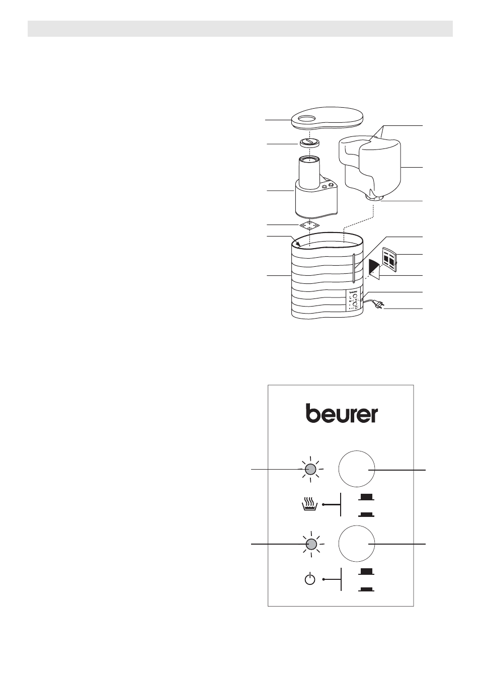
Humidifier
1 Cover
2 Steam
nozzle
3 Steam
tower
4 Pad
(beneath the steam tower in the
hot water chamber)
5 Hot
water
chamber
(beneath the steam tower, not
illustrated)
6 Humidifier
casing
7
Water tank handles
8
Water tank, volume 5 litres
9
Tank catch, with valve
10
Water level indicator
11
Air filter flap (back of appliance)
12
Black air filter (back of appliance)
13 Control
panel
(see diagram below)
14
Cable with mains plug
(back of appliance)
1
2
3
4
5
6
12
11
10
9
8
7
13
14
Control panel
A
Red indicator illuminated when
water tank is empty
B
Green indicator illuminated when
humidifier is switched on
C
Steam button for regulating
humidity
• Button depressed: 400 ml/h
(maximum steam)
• Button released: 150 ml/h
(minimum steam)
D
ON/OFF button for switching
humidifier on and off
• Button depressed: Appliance
is switched on
• Button released: Appliance is
switched off
OFF
ON
I
II
A
B
C
D