BrightSign HD120 Hardware User Manual
Page 10
BrightSign HD120, HD220, HD1020
7
All information provided in this reference manual applies to products under development. The characteristics and specifications of these products are subject to
change without notice. BrightSign assumes no obligation regarding future manufacturing unless otherwise agreed to in writing. © BrightSign LLC, 2012
1 out driving 1 in
V=3.3*100/(100+1,000)=0.3
1 out driving 2 in
V=3.3*100/(100+500)=0.55
1 out driving 3 in
V=3.3*100/(100+333.3)=0.76
1 out driving 4 in
V=3.3*100/(100+250)=.94 (This is too high, so 1 output
driving 3 inputs is the maximum)
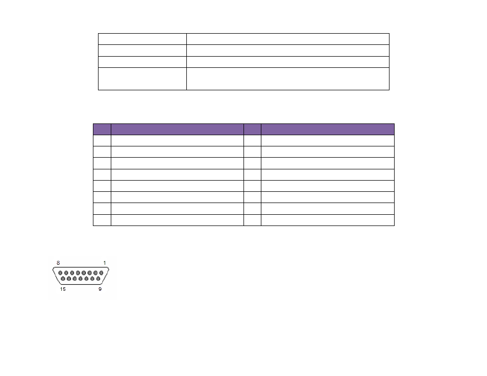
The following table illustrates the pinout of the DA15 on the HD series of players:
pin
Description
pin
Description
1 IR blaster input
2 Ground
3 Button 6 I/O
4 Button 5 I/O
5 Button 3 I/O
6 Ground
7 Button 1 I/O
8 +3.3V output at 500mA
9 Ground
10 Button 7 I/O
11 Ground
12 Button 4 I/O
13 Button 2 I/O
14 Ground
15 Button 0 I/O
--
--
Here is the DA15 female as viewed from the front of the BrightSign HD120 and HD1020:
A button/LED/IR board can be used to demonstrate the GPIO and IR functions on a BrightSign player. This board is built
by a third-party manufacturer and can be purchased upon request.