On-board switch, Reset switch/gpio button – BrightSign HD120 Hardware User Manual
Page 20
BrightSign HD120, HD220, HD1020
17
All information provided in this reference manual applies to products under development. The characteristics and specifications of these products are subject to
change without notice. BrightSign assumes no obligation regarding future manufacturing unless otherwise agreed to in writing. © BrightSign LLC, 2012
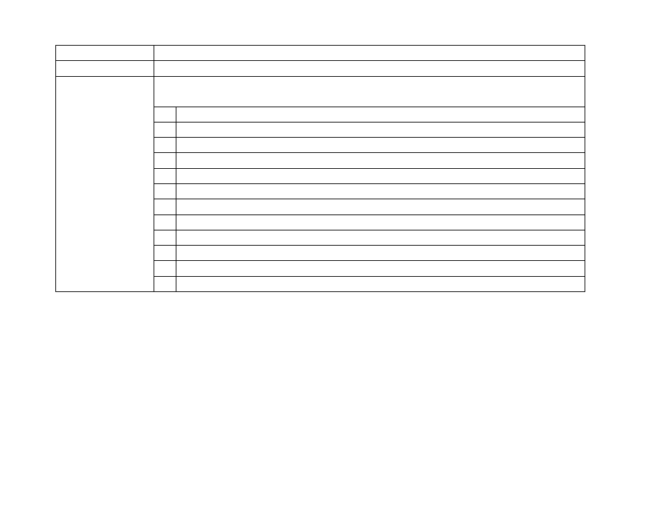
Green flash activity Flashes any time there is CPU activity.
Yellow update
Flashes when the board is being upgraded.
Red status
Flashes a certain number of times to indicate which error is occurring. The flash codes are
described below.
2 Unspecified error
3 Network recovery script is preparing to run on a device configured for network recovery.
4 No upgrade file found
5 Failed to load kernel module
6 Board is not capable of running the current firmware version.
7 Problem related to the Ethernet chip
7 A piece of on-board hardware is not working correctly (on firmware versions 4.1 and later).
8 Problem related to the storage device (either the USB drive or SD card)
9 Problem related to the registry/EEPROM
10 The autorun script encountered a load/run error.
11 WiFi-related error (mainly, WiFi not found on USB)
12 Unable to find a bootable image (on firmware versions 4.0 and later)
On-Board Switch
The on-board switch is connected to the GPIO32. A pullup on the button normally sets the GPIO32 to be pulled high.
Conversely, the GPIO32 is pulled low when the button is pressed.
Reset Switch/GPIO Button
The on-board switch is connected to the GPIO12. Pressing down the reset button will cause the GPIO12 to go low.
Holding the reset button low for approximately 10 seconds will cause a hard reset. When the board goes into reset mode,
the power LED will be dark until the reset button is released.