1 instrument – Bronkhorst CoriCalc User Manual
Page 8
page 8
9.17.056
4.1.1
Instrument
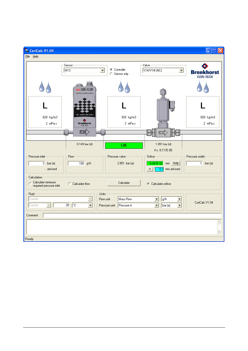
Example of controller for water application.
Figure 2 - The CoriCalc main window for controller calculations for a liquid
The upper part of the window shows a schematic overview of a (mini) CORI-FLOW® instrument. For a meter, only the
sensor part is shown, whereas both the sensor and the valve are shown for a controller.
Above the sensor image, the desired sensor for which a calculation is to be made, can be selected from the Sensor list.
In case Controller is selected, a valve can be selected from the Valve list.
Apart from choosing a specific sensor and/or valve for making calculations, Advise… can be selected to get CoriCalc an
advice for the right sensor or valve.
After a calculation has been performed, this part also shows the phase of the fluid at two (sensor only) or three
(controller) positions in the instrument, at the inlet, between the sensor and the valve and at the outlet. Graphically
the phases are indicated by bubbles for gases and droplets for liquids. At these positions two important fluid
properties (the density in kg/m
3
and the viscosity in mPa.s) are shown as well.