Soundweb, Rear panel details – BSS Audio sw9088iis Install Guide User Manual
Page 5
131
Soundweb
TM
DCD
DSR
RX
RTS
TX
GROUND
CTS
DTR
N/C
Rear panel details
Mains inlet
Mains inlet
Mains inlet
Mains inlet
Mains inlet
IEC power connector for removable mains supply.
Fuse holder
Fuse holder
Fuse holder
Fuse holder
Fuse holder
Mains fuse - requires a 20mm T1A type fuse.
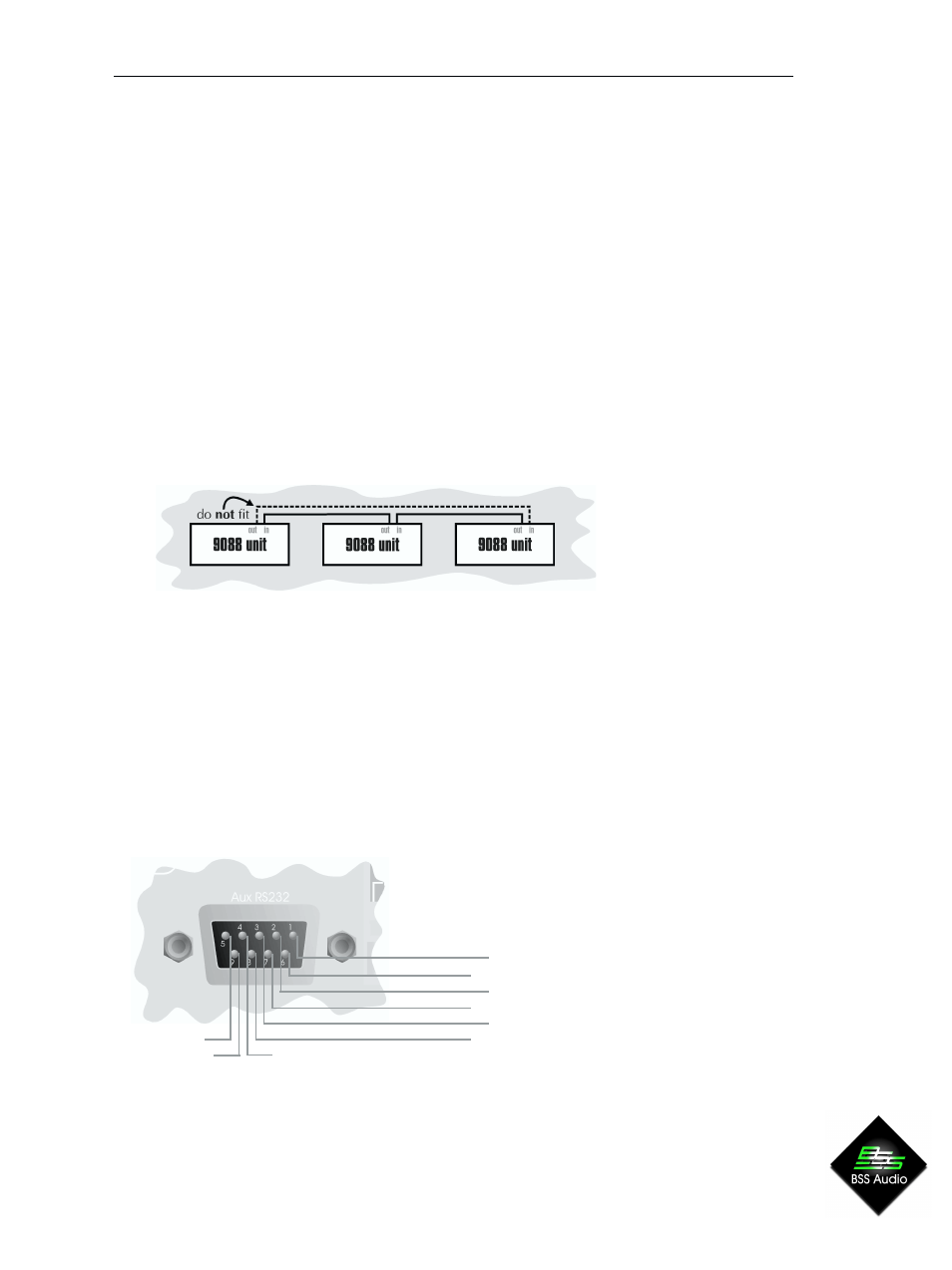
Network In/Out
Network In/Out
Network In/Out
Network In/Out
Network In/Out
Network In - connects to the Network Out socket on another unit. Connecting multiple
units is done in the same way - In to Out. This allows audio channels to be passed
‘downstream’ from the Net Out socket on one device to the Net In socket on the next
device. The Soundweb system automatically completes this ‘daisy chain’ of device
connections to form a loop (using a back-channel), as shown by the dotted line in the
diagram below. This shows that audio channels may be routed back from the terminal
device (the one without a connection on its Net Out socket) to the first device (the one
without a connection on its Net In socket). There must be no physical cable connection
between these two end devices however.
The connecting cable is CAT. 5 network cable, terminated with RJ45 connectors, with all
8 cores wired straight through.
Note that the twisted pairs in any CAT.5 network cable must be wired to the following pin
pairs at each terminal:
1 (White-Orange) with 2 (Orange)
3 (White-Green) with 6 (Green)
4 (Blue) with 5 (White-Blue)
7 (White-Brown) with 8 (Brown)
Aux RS232
Aux RS232
Aux RS232
Aux RS232
Aux RS232
This is for connection to a PC, modem or AMX panel (a control PC may be connected
here, or via the front panel RS232 port).