Control inputs – BSS Audio BLU-GPX Owner's Manual User Manual
Page 8
8
Control Inputs
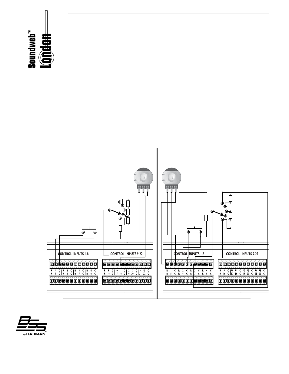
2-wire mode
In this mode, the CONTROL INPUTS are internally ‘pulled up’ to +5V DC via a 4.7kOhm
resistor. Therefore, no external voltage source is needed to create contact closure to
ground for switches such as mute buttons or, resistance to ground (for other multi-state or
continuous controls such as Parameter Presets or faders).
See the Soundweb London help for a table of resistor values for use with Parameter
Presets or source selectors.
A ‘common’ ground connection (C) is provided for every CONTROL INPUT.
A 47kOhm-log potentiometer (Part no. DM10018) connected between a control input
and common will allow parameters to be controlled linearly.
3-wire mode
This mode allows the use of linear pots or faders for continuous controls. A pot would be
wired as a potential divider with the top of the track connected to the reference output
R, the wiper to a control input and the bottom of the track to a common C. For good
performance, pots with track resistance between 10K and 100KOhms are recommended.
2 Wire Mode
3 Wire Mode
Logic & Opto Outputs
Relay Outputs
LED
+supply voltage
ground
switch
3600R
1800R
1200R
unconnected
ladder
47kOhm
log
potentiometer
470R
10K-100kOhm
linear
potentiometer
switch
1k
1k
1k
ladder
1k
4k7
relay
coil
relay
coil
NC = Normally Closed
NO = Normally Open
C = Common
relay
NC
C
NO