BSS Audio DPR-402 Owner's Manual User Manual
Page 17
17
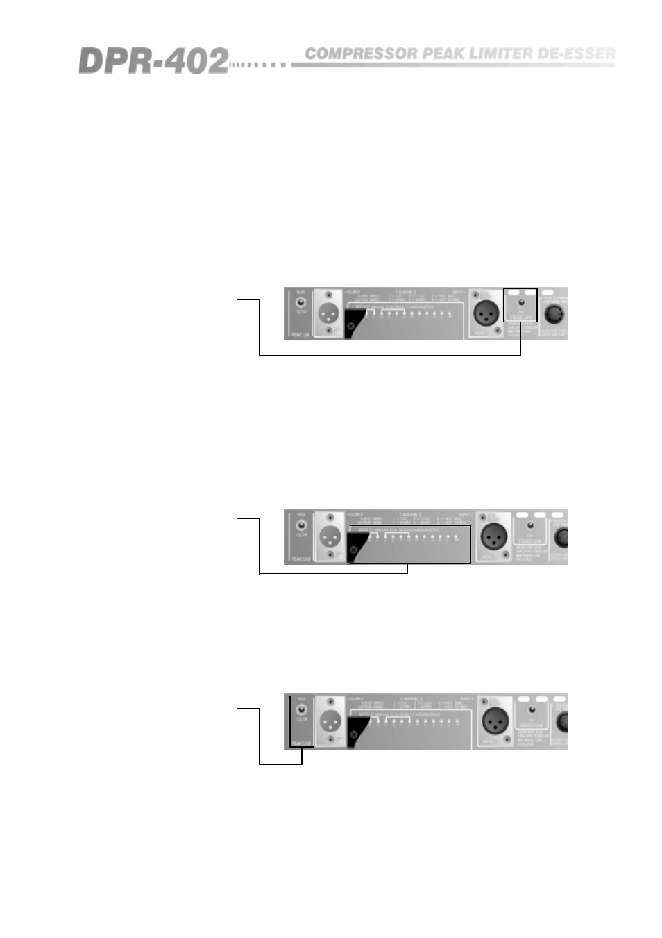
9.3 Stereo Link
This facility (See figure 9.4) enables the two channels of the DPR-402 to be
used in a stereo system, with the result that there is no image shifting under
comparison on either channel. This switch actually couples the detector
outputs from both channels together, so that either one responds to the largest
signal present. When in stereo mode, the front panel 'LINK' LED will
illuminate, and care should be taken to ensure that both channels have their
controls set equally. For other methods of multiple channel coupling, refer to
section 14.
9.4 Barrier Strip
This interface facility (See figure 9.5) provides various input and output
signals to the unit, allowing other dynamic controlling features to be realised.
This strip also includes the two insertion points for external equipment
connections, and in the absence of these, the two indicated shorting links
must be made to allow normal operation of the unit. Please refer to section 14
for examples of possible uses.
Fig 9.5 Barrier Strip
9.5 Peak Limiter
Switch
This fast/slow selector (See figure 9.6) changes the dynamic response of the
peak limiter section to best suit the particular program material. Please refer
to section 12.4 for applications and usage.
Fig 9.6 Peak Limiter
Switch
Fig 9.4 Stereo Link
Switch