7 bypass switch, 8 mode switch – BSS Audio DPR-402 Owner's Manual User Manual
Page 21
21
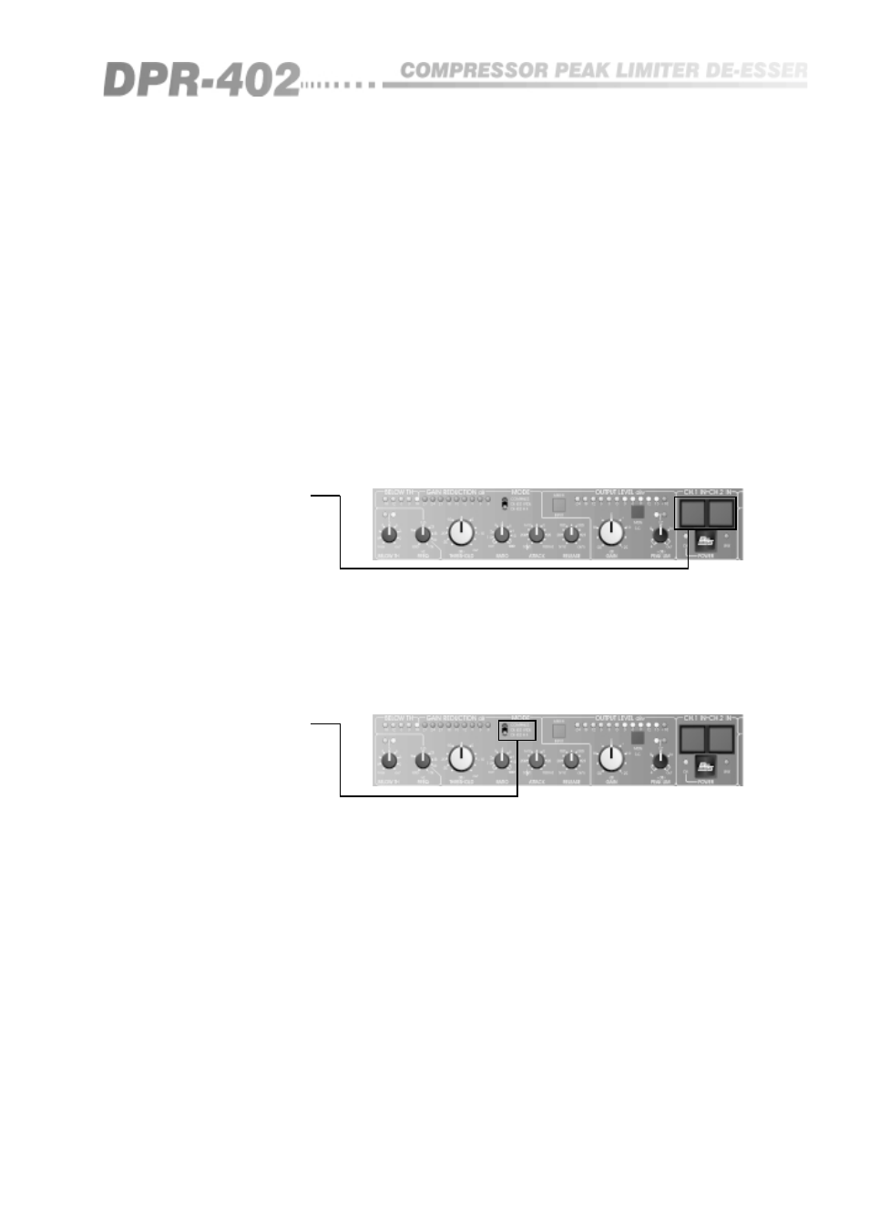
The BYPASS switch (See figure 10.8) enables you to bypass quickly all
functions of the DPR-402 by connecting the output directly to the input. When
the switch is pressed, and the light is on, all DPR-402 functions are present on
the output signal. When the switch is out, all facilities are bypassed.
It should be noted that in the bypass mode, the input is still connected to all
of the DPR-402 circuitry, so that all of the required facilities can be selected
and set up. This, in conjunction with the OUTPUT METER and INPUT
SWITCH, provides a powerful tool for comparing processed signals prior to
operating the bypass switch and going 'on-air'.
A further feature of this illuminated switch is to allow coding of each
particular channel with a specific number or letter. By removing the lens-cap
with a small screwdriver or your fingernail, an appropriate symbol can be
fitted. This will have particular advantages in situations where more than one
DPR-402 is fitted into a control rack.
10.7 BYPASS switch
Fig 10.8 BYPASS switch
This control switch (See figure 10.9) reconfigures the compressor to insert the
built-in filters into its side chains, so that gain reduction only occurs when
certain frequencies are present in the input signal.
For normal compression, this switch will always be in the 'compress' position.
Please refer to sections 12.2 and 12.3 for a full explanation of this, and the
applications of de-essing.
10.8 MODE switch
Fig 10.9 MODE switch