8 ....... setup diagram, Setup diagram – BUG-O Systems MM-1 User Manual
Page 8
Advertising
8
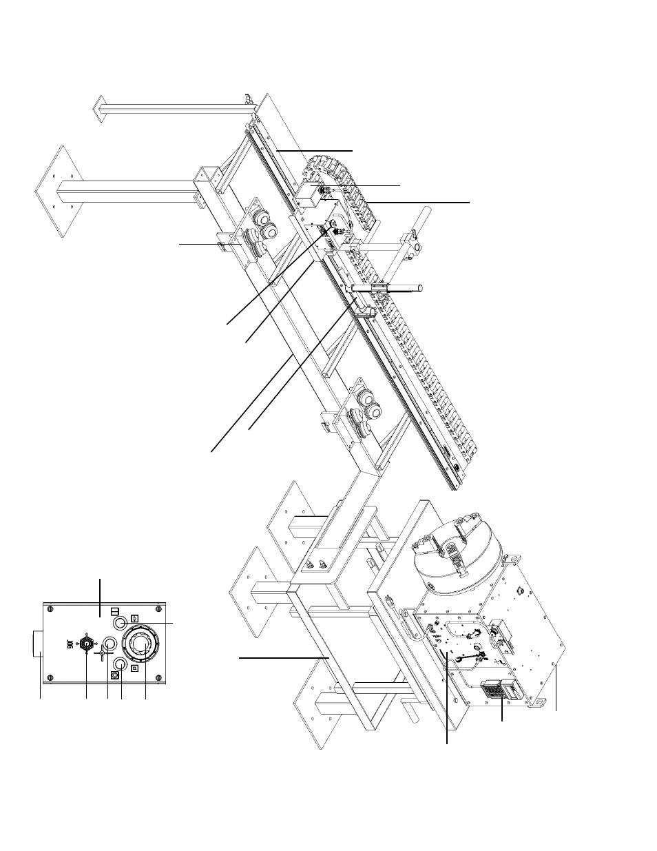
SETUP DIAGRAM
HEADST
OCK
PRO
GRAMMI
NG
PENDANT
CO
NT
RO
L
PANEL
ENCODER
CABLE
SUPPORT
RAIL
ROLLER BLOCK
ASSEMBL
Y
DRIVE CARRIAGE
CLUTCH
DRIVE
CARRIAGE
ST
ANDARD
PIPE
BED ASSEMBL
Y
TORCH
HOLDER
ADJUST
ABL
E
TABLE
Reset
Stop /Pause
Start / Resume
Manual Jog
Speed
Control
Panel Connector
OPERA
TOR
REMOTE
PENDANT
Advertising