Installation – Campomatic C64EWR User Manual
Page 6
6
INSTALLATION
POSITIONING
•
Remove all packing materials
including the protective film covering
the chrome-plated and stainless steel
parts (if applicable).
•
The kitchen should be dry and well
ventilated. Position the cooker
ensuring free access to all the
controls.
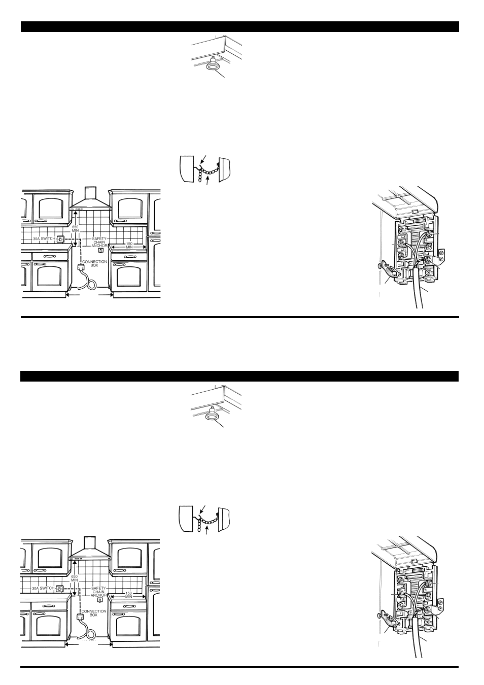
•
The distance between the hob and
extractor hood should be at least
650mm.
•
If necessary level the cooker by the
adjustable feet.
Figure 2
550 MIN
In order to eliminate the risk of the cooker
falling forward a chain has been installed
at the rear side of the cooker. This should
be fastened securely to the wall behind
the appliance with the bracket supplied
(Figure 4).
Figure 3
ADJUSTABLE
FOOT
Figure 4
ELECTRICAL CONNECTIONS
The cooker must be properly
connected to the mains supply by a
qualified electrician according to
current safety regulations. Do not
modify or change the cooker in any
way.
Before the cooker is connected to the
mains supply make sure:
The mains voltage is the same as that
specified on the data plate on the cooker.
The mains supply cable is rated for the
maximum power consumed by the
appliance as specified on the data plate
on the cooker.
The appliance must be installed using a
double pole switch of 45A minimum
capacity, with 3mm minimum contact
separation between poles.
Connect the cooker to the mains
connection box following the colour code:
Yellow/green wire should be connected to
earth terminal marked E or E.
Blue wire should be connected to the
neutral terminal marked N.
Brown wire should be connected to live
terminal
marked L.
Ensure that
connections are
tight and that
no loose
strands are left
out of the
terminals.
No lead must
touch hot
surfaces over
75°C.
E or
E
L
N
CLAMP
MAINS
SUPPLY
Figure 5
25982-25 5 7.qxp 2 / 6/2
7 7:23 Page 6
6
INSTALLATION
POSITIONING
•
Remove all packing materials
including the protective film covering
the chrome-plated and stainless steel
parts (if applicable).
•
The kitchen should be dry and well
ventilated. Position the cooker
ensuring free access to all the
controls.
•
The distance between the hob and
extractor hood should be at least
650mm.
•
If necessary level the cooker by the
adjustable feet.
Figure 2
550 MIN
In order to eliminate the risk of the cooker
falling forward a chain has been installed
at the rear side of the cooker. This should
be fastened securely to the wall behind
the appliance with the bracket supplied
(Figure 4).
Figure 3
ADJUSTABLE
FOOT
Figure 4
ELECTRICAL CONNECTIONS
The cooker must be properly
connected to the mains supply by a
qualified electrician according to
current safety regulations. Do not
modify or change the cooker in any
way.
Before the cooker is connected to the
mains supply make sure:
The mains voltage is the same as that
specified on the data plate on the cooker.
The mains supply cable is rated for the
maximum power consumed by the
appliance as specified on the data plate
on the cooker.
The appliance must be installed using a
double pole switch of 45A minimum
capacity, with 3mm minimum contact
separation between poles.
Connect the cooker to the mains
connection box following the colour code:
Yellow/green wire should be connected to
earth terminal marked E or E.
Blue wire should be connected to the
neutral terminal marked N.
Brown wire should be connected to live
terminal
marked L.
Ensure that
connections are
tight and that
no loose
strands are left
out of the
terminals.
No lead must
touch hot
surfaces over
75°C.
E or
E
L
N
CLAMP
MAINS
SUPPLY
Figure 5