Trouble shooting, Tips & tricks, Step 2 – Cetacea Sound Astronaut 001 Long-Run Power Kit User Manual
Page 2: Step 3, Step 1, Source connection, Power connection, Ceiling mounting instructions
Trouble Shooting
NOISE:
Make sure all cable connections are tight.
NO SOUND:
Verify that the GREEN light is on at the speaker
input panel. Verify the sound source is “ON” and playing.
Tips & Tricks
Do not disconnect source cables while speaker is powered up. This will result in unwanted noise.
The built-in mixer is for multiple connection convenience only. Do not play more than
one input at a time or severe damage may occur to the speaker.
Do not play the Astronaut at full volume. If it is not loud enough before sounding distorted, the room
may require two speakers for adequate sound coverage. Prolonged distortion will eventually cause
severe damage to the speaker
Cetacea PAL microphones are designed and matched to our equipment. Use of other brands of
microphones is not advised.
Find a more complete guide to trouble shooting on our website.
www.cetaceasound.com/literature.htm > Troubleshooting Guides
Find a more complete list of Tips and Tricks on our website.
Technical Support
Before contacting Cetacea Sound Corp for technical support please read our Customer Service and
Diagnostic Procedures, which can be found on our website.
www.cetaceasound.com/custservice.htm
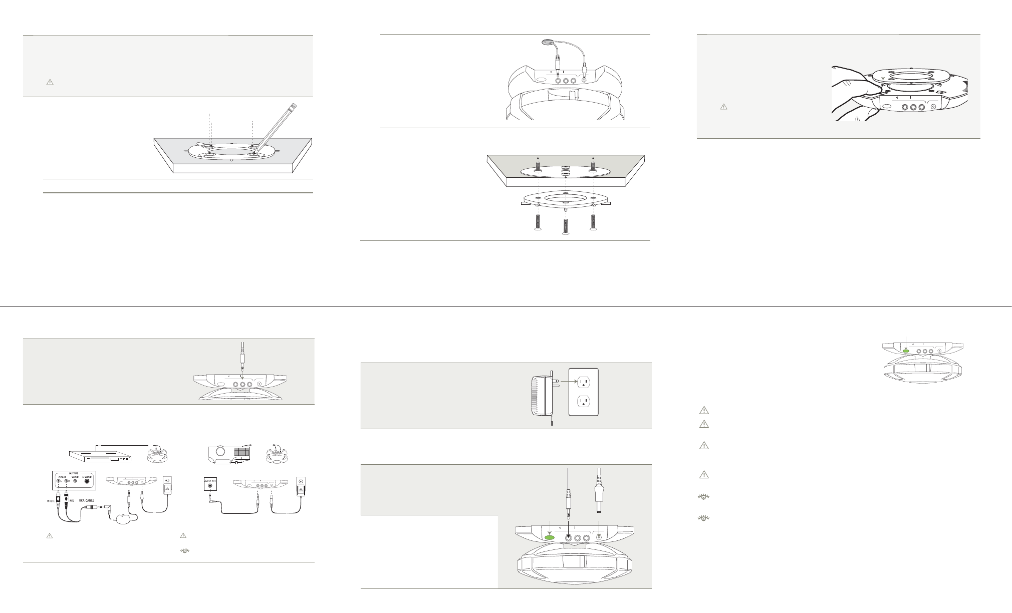
Step 2
Source Connection
2-1
Cables & Connections
Run the source cable to the Astronaut with
high quality cables and connectors. The
Astronaut has a built in 3-channel mixer and
any input (A, B, or C) can be used. Jacks are
3.5mm minis.
T W I S T
I N P U T
A
B
C
DC PWR
2-2
Connection Diagrams
Stereo VCR/DVD Connections
(Line Level - Fixed Output)
AC
OUTLET
SPEAKER CONNECTIONS
STEREO VCR/DVD CONNECTIONS
VOL
T W I S T
I N P U T
A
B
C
DC PWR
Some equipment may have variable output.
Projector Connections
(Variable Output)
AC
OUTLET
SPEAKER
CONNECTIONS
PROJECTOR
CONNECTIONS
T W I S T
I N P U T
A
B
C
DC PWR
CAUTION: Not all projectors have suitable
audio outputs.
See website for additional information.
Step 3
Power Connection
NOTE: DO NOT connect speaker to power until after Steps 1 & 2 have been completed and at
least one source cable is connected.
3-1
High Voltage Connection
Long Run Power Supply
#FW-PSE15WNC
3-2
Distance To Power Source
Make sure there is an AC outlet within 40' of the speaker. When connecting the cable to the power
supply, black is negative, white is positive.
3-3
Low Voltage Connection
The low power barrel connector (Fig. G)
can now be plugged into the speaker.
Plugging/unplugging this connector will
turn the speaker on and off.
T W I S T
I N P U T
A
B
C
DC PWR
Fig. G
Fig. H
3-4
Power Up
When the connector barrel is plugged
into the speaker the internal GREEN
light (Fig. H) will turn on, indicating the
speaker is on. Turn on your sound and
adjust the volume.
T W I S T
I N P U T
A
B
C
DC PWR
Step 1
Ceiling Mounting Instructions
1-1
Speaker Location
Locate an appropriate location on the ceiling. The Astronaut can be located anywhere on the
ceiling and does not need to be in the center of the room to sound the best. Try to maintain at
least 4 feet of space from the nearest wall or vertical obstruction.
CAUTION: INSTALL SPEAKERS IN A SAFE PLACE. AWAY FROM DIRECT HEAT, HIGH
HUMIDITY AND PHYSICAL OBSTRUCTIONS.
1-2
Mounting Bracket
Remove a ceiling tile and set it on a
fi rm surface. Use the ceiling bracket
as a guide, mark the location where
you will drill ¼" holes.
Drill or tap the ¼" holes in the ceiling surface.
1-2
cont.
If cables will be routed above the
ceiling, cut a 1" hole. Allow 6" of
clearance between the front of the
speaker and the hole.
T W I S T
I N P U T
A
B
C
DC PWR
Attach the ceiling plate (Fig. A)
above the ceiling tile and the
mounting bracket (Fig. B) below
the ceiling using four aluminum
bolts (Fig. C). The bolts should be
snug; do not over-tighten.
NOTE: If attaching the Astronaut
to a solid ceiling, the ceiling plate is
not used and the 4 aluminum bolts
must be replaced with similar sized
wood or plaster screws.
Fig. B
Fig. C
Fig. A
1-4
Attach Astronaut Speaker
Attach the Astronaut speaker to the
mounting bracket on the ceiling.
Use one fi nger to feel the fi rst peg
(Fig. D). Align it with a hole (Fig.
E) and then the others will easily
follow.
Make sure all 4 pegs are aligned
and the speaker is fi tting fl ush to
the ceiling before the fi nal step
below.
T W I S T
I N P U T
A
B
C
DC PWR
Fig. D
Fig. E
Tools that may be required to mount the Astronaut to a suspended ceiling:
Phillips head screwdriver
Hand drill with ¼” bit
Measuring tape
Installer Notes
www.cetaceasound.com/literature.htm > Installation Guides
See the Getting Started Guide for additional information about input sensitivities.
Also see our website for installer advice. www.cetacea.com/literature.htm > Installation Guides
Please save the boxes in case you need to return the Astronaut for any reason.
PLEASE READ THIS GUIDE THOROUGHLY & VISIT OUR WEBSITE FOR ADDITIONAL INFORMATION.
PLEASE READ THIS GUIDE THOROUGHLY & VISIT OUR WEBSITE FOR ADDITIONAL INFORMATION.
PLEASE READ THIS GUIDE THOROUGHLY & VISIT OUR WEBSITE FOR ADDITIONAL INFORMATION.