Installation, Mechanical, Ventilation – Cloud Electronics CXV-225 User Manual
Page 8: Connections and adjustments inputs, Sensitivity and gain control input routing
CXV-225 & CXV-425 User Manual v1.0
8
Installation
Mechanical
The amplifiers are designed to be mounted in a standard
19” equipment rack. The front panel is fitted with rackmount
ears for this purpose. The CXV-225 requires 2U of vertical
rack space, the CXV-425 requires 3U. See notes below
regarding spacing and ventilation.
Due to the units’ weight, the use of additional side supports
is recommended.
Ventilation
The CXV-425 is force cooled by two thermostatically-
controlled fans mounted on the rear panel. The fan is
operative at all times, remaining at low speed at internal
temperatures below 50 °C, then increasing in speed above
this temperature to a maximum speed at 70 °C.
The CXV-225 has a single fan mounted internally to keep
noise to a minimum.
Always allow adequate space around the amplifier(s) to
allow a free flow of air through the unit(s). Ensure that cable
bundles or other items do not obstruct any grilles.
In 19” rack applications we recommend leaving 1U of rack
space above and below each unit. Plain 1U blank panels,
not slotted ventilation panels should be used, as the latter
reduce the effect of forced-air cooling. The direction of
airflow is from front-to-rear (CXV-425) and front-to-sides
(CXV-225); it is recommended not to mix these amplifiers
with other equipment employing forced-air cooling which
acts in the opposite direction within the same rack.
Connections and Adjustments
Inputs
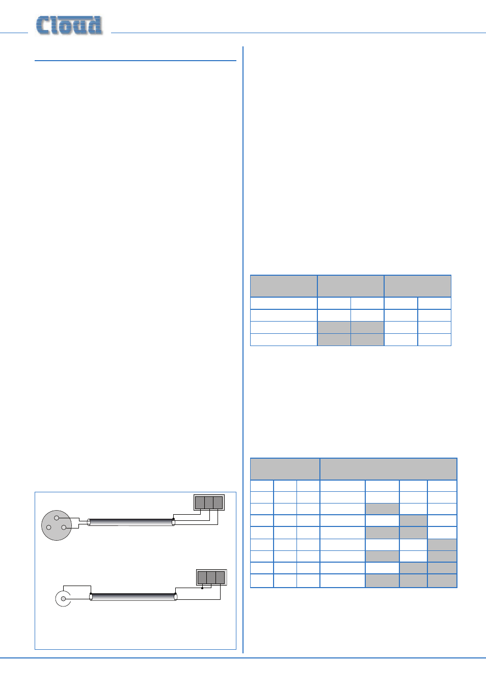
Each amplifier channel has an electronically-balanced input
on a 3-pin 3.5 mm-pitch screw terminal connector. Twin-
core screened cable should be used when driving the
amplifier inputs from a device with a balanced output. Single-
core screened cable can be used when connecting to an
unbalanced source.
Sensitivity and Gain Control
Control of input level is provided by a preset rotary
control adjacent to each input connector. The control
should be adjusted using a trim tool or small screwdriver.
Full attenuation of the input signal – i.e., zero output – is
obtained with the control fully anti-clockwise. Maximum
sensitivity is with the control fully clockwise; at this setting
the maximum output level of 100 Vrms will be produced for
an input signal level of 0.775 Vrms (0 dBu).
We recommend that the level for each channel should
be adjusted after installation is complete to ensure that
adequate, but not excessive sound levels are achieved with
the programme material that will be used in practice.
Input Routing
To facilitate the use of the amplifiers in multi-zone
applications, input selection switches are provided on all
channels except Ch1. This gives the installer an easy method
of paralleling channels from a single input.
The options are summarised in the table below:
CHANNEL
SOURCE
CXV-225
CXV-425
Button position
Out
In
Out
In
Channel 2
Input 1
Input 2
Input 1
Input 2
Channel 3
Input 1
Input 3
Channel 4
Input 2* Input 4
* post Ch 2 switch
Refer also to the block diagram on page 5
CXV-225 only: The CXV-225’s single switch allows
Channel 2 to be operated in parallel with Channel 1, with
Input 1 acting as the common input connector.
CXV-425 only: The three switches on the CXV-425 allow
a total of 8 routing possibilities, including 4-channel, dual
stereo and mono operation with 4 channels paralleled. The
table below clarifies the options:
BUTTON
POSITION
INPUT ROUTING: CHANNELS
FED By EACH INPUT
Ch 1 Ch 2 Ch 3 Input 1
Input 2
Input 3 Input 4
In
In
In
Ch 1
Ch 2
Ch 3
Ch 4
Out
In
In
Chs 1 & 2
Ch 3
Ch 4
In
Out
In
Chs 1 & 3
Ch 2
Ch 4
Out
Out
In
Chs 1, 2 & 3
Ch 4
In
In
Out
Ch 1
Chs 2 & 4 Ch 3
Out
In
Out
Chs 1, 2 & 4
Ch 3
In
Out
Out
Chs 1 & 3
Chs 2 & 4
Out
Out
Out
Chs 1, 2, 3 & 4
1
2
3
Balanced output
(typically XLR):
pin 1: ground
pin 2: hot
pin 3: cold
Amplifier input
1
2
3
+
-
+
-
pin 1: n/c
pin 3: hot
pin 2: cold
BALANCED CONNECTION
Amplifier input
1
2
3
+
-
pin 1: n/c
pin 3: hot
pin 2: cold
Unbalanced outputs
(e.g. phonos):
screen: ground
pin: hot
UNBALANCED CONNECTION
fig.6: Input wiring