Remote control of level, Outputs, Connect as shown below – Cloud Electronics CXV-225 User Manual
Page 9
CXV-225 & CXV-425 User Manual v1.0
9
Remote Control of Level
The CXV-225 and CXV-425 amplifiers are compatible with
standard Cloud remote control plates type RL-1, allowing
control of level from a remote position. In order to use
the amplifiers with the RL-1, VCA cards must first be fitted
in the channels to be controlled remotely. See page 10 for
details of VCA cards and fitting. Once VCA cards have been
fitted, RL-1s may be connected at the rear 3-pin 5 mm-pitch
screw terminal connectors (Remote Level), using the wiring
shown below.
1 2 3
REMOTE LEVEL
CONNECTOR
1 2 3
RL-1
USE TWO-CORE SCREENED CABLE
Use two-core screened cable to connect the remote level
plate (maximum length 100 metres).
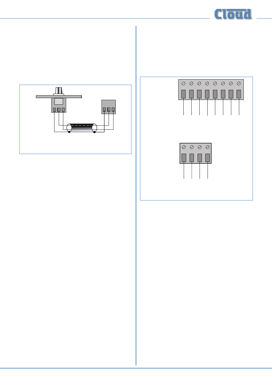
Outputs
The 100 V line speaker output terminals are behind the
removable output terminal cover (see page 7). The covers
are fitted with a cable gland (one per channel); to use these,
slacken the rear nut by a few turns and feed the cable
through. The plug-in connectors are suitable for cable cores
up to 2.5 mm
2
.
Connect as shown below:
-
+
-
+
CH 1
CH 2
-
+
CH 1
CH 2
-
+
-
+
-
+
-
+
CH 3
CH 4
CXV-425
CXV-225
1
2
3
4
1
2
3
4
6
7
8
5
After making the connections, replace the cover and tighten
the gland nuts. They only need to be firmly finger-tight; take
care not to over tighten, use only enough torque to give
reasonable cable retention. Do not use a spanner.
Caution: The amplifier should never be operated without
the output terminal cover installed. Apart from exposing
the high voltage terminals, leaving the cover off also
compromises the amplifier’s forced-air cooling.
The amplifier’s transformerless output stage is designed
to drive up to 100 Vrms into an impedance of at least
40 ohms (each channel). Check the input impedance of the
loudspeaker type in use and divide this figure by the number
of loudspeakers* to ensure that the total impedance is
greater than 40 ohms. Alternatively, add the wattages of all
the loudspeakers being driven by each channel (taking power
tappings into account); the total must be less than 250 W.
* Assumes all loudspeakers in the system are of the same type and have the
same tap setting.
fig.7: Remote level control wiring
fig.8: Output wiring