Control (paging access) connection – Cloud Electronics PM1 User Manual
Page 10
PM1 Installation and User Guide v1.0
10
Note that the mic capsule is a dynamic type and no phantom power is required.
Ensure that the microphone input used does NOT have phantom power enabled as
damage to the capsule may result from the inadvertent application of a DC voltage.
Control (paging access) connection
If using two separate cables, the control cable may be any suitable two-core cable,
though the use of single-core or twin-core screened cable is preferred (especially if
the microphone is more than a few metres from the host mixer). Many installers will
choose to use a second run of microphone cable, which provides a neat appearance.
The control cable should be fed through the right-hand cable clamp (looking from
the rear of the unit), and connected to the right-hand screw-terminal block (marked
ACCESS) on the internal PCB.
Connect to the terminal block as follows:
TERMINAL
USE
TYPICAL CABLE COLOUR
0V/COMMON
Switch common contact (C)
Screen
ACCESS N/C
Switch normally-closed contact (NC)
Core*
ACCESS N/O
Switch normally-open contact (NO)
*Connect the core to either N/O or N/C, not both. See following text.
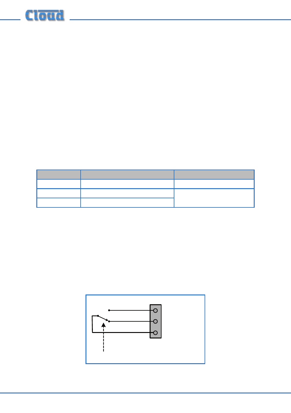
Connect the control cable to the 0V/COMMON terminal and either the ACCESS
N/C or the ACCESS N/O terminal. The PTT (Press-To Talk) switch is fitted with both
types of contact (see diagram below); use whichever the host mixer’s Access Port
requires (consult the Installation Guide for the mixer to confirm the convention
used). All Cloud mixers and zoners require the use of external NO contacts for
paging access, so use the ACCESS N/O terminal if connecting the PM1 to a Cloud
host unit.
PRESS TO TALK
C
NC
NO
0V/COMMON
ACCESS N/O
ACCESS N/C
U3