Cloud Electronics PM1 User Manual
Page 11
PM1 Installation and User Guide v1.0
11
The other end of the control cable should be connected to the host mixer’s Access
Port. It may be necessary to configure the mixer for correct operation with a paging
microphone. Mixers/zoners with more than one microphone input will probably have
an Access Port catering for each input; be sure to connect the control cable to the
terminal related to the microphone input being used. Again, all recent Cloud mixers
and zoners are designed for use with paging microphones and connecting to and
configuring them is straightforward.
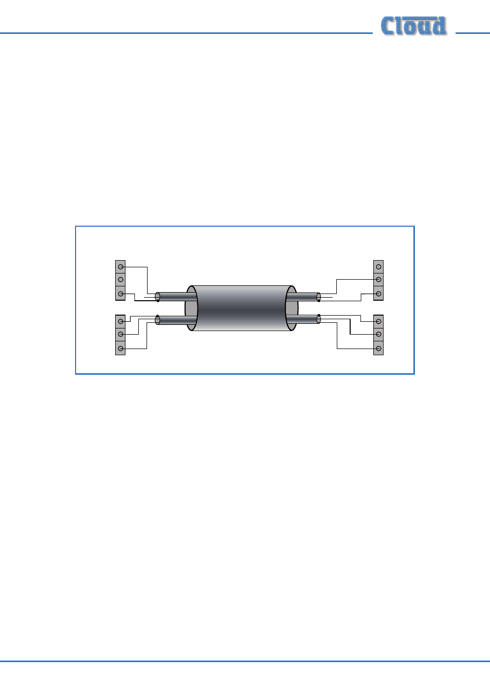
Typical example
The example shown below illustrates the connection of a PM1 to a Cloud CX261
mixer. It is assumed that MIC 1 input is used.
U2 AUDIO
U3 ACCESS
PM1
CLOUD CX261
HOT
COLD
SCREEN
0V
N/C
N/O
MIC 1 INPUT
ACCESS PORT
3
2
1
0V
M1
M2
In the example, 2-pair cable is employed, with separate screened twin-and-screen
cores for the Audio and Access connectors. The PM1’s audio output is wired pin-to-
pin to the MIC 1 INPUT connector on the CX261. The access connector is wired to
the CX261’s Access Port, the ground terminal being connected to 0V on the host via
the cable screen and the N/O terminal to M1.
Use this same wiring arrangement if using two separate cables.
In addition, the CX261’s internal jumpers will need to be set to enable the Access
Port and to set the Mic 1 priority circuit for access triggering. The CX261’s own User
Guide fully describes this procedure. It is likely that similar adjustments will need to
be made with all makes and models of host mixer; the unit’s documentation should
be consulted in all cases.