11 technical specifications – Cloud Electronics CX242 User Manual
Page 11
CX242: I
NSTALLATION AND OPERATION MANUAL
10
With no external connection to pin 3, an internal 15k resistor connected to the +15V
power will ‘pull up’ the source select control voltage and the ‘off’ position will be selected.
The output impedance of the control voltage source should be low enough to overcome
the influence of this resistor. If you require to fix the music signal to the Line 1 input, wire
a 20k resistor between pins 1 & 3 on the remote control connector.
If the control voltages are not isolated, there is a small risk of creating a ‘ground loop’ by
linking the CX242 ground with the ground of the equipment providing the control voltages;
we suggest that all pieces of equipment be positioned in close proximity.
11 Technical
Specifications
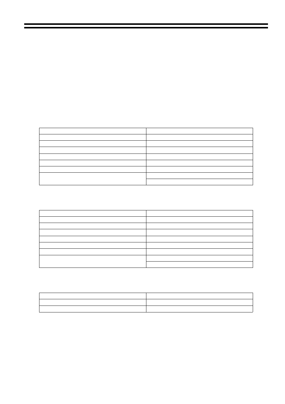
Stereo Line Inputs
Frequency Response
20Hz-20kHz ±0.5dB
Distortion <0.05%
20Hz-20kHz
Nominal input level
0dBu/775mV
Input impedance
100k
Ω
Input gain
±12dB
Headroom >20dB
Noise
-90dB A weighted (0dB gain)
HF ±10dB 10kHz
Equalisation
LF ±10dB 50Hz
Microphone Inputs
Frequency Response
100Hz-20kHz ±0.5dB
Distortion <0.03%
20Hz-20kHz
Gain range
0dB-60dB
Input impedance
>2k
Ω (balanced)
Common mode rejection
>70dB 1kHz
Headroom >20dB
Noise
-122dB EIN 22Hz-22kHz (150
Ω)
HF ±10dB 5kHz
Equalisation
LF ±10dB 100Hz
Zone outputs
Nominal output level
0dBu balanced, -6dBu unbalanced
Minimum load impedance
600
Ω
Maximum output level
+26dBu balanced, +20dBu unbalanced
15/07/02 V4