2 general, 3 schematic diagram, 4 installation – Cloud Electronics Matrix4 User Manual
Page 3: 5 microphone inputs
2
Matrix 4 I
NSTALLATION AND OPERATION MANUAL
1 Safety
Notes
• Do not expose the unit to water or moisture.
• Do not expose the unit to naked flames.
• Do not block or restrict any air vent.
• Do not operate the unit in ambient temperatures above 35 C.
o
• Do not perform any internal adjustments unless you are qualified to do so and fully
understand the hazards associated with mains operated equipment.
• The unit has no user serviceable parts. Refer any servicing to qualified service
personnel.
• If the moulded plug is cut off the lead for any reason, the discarded plug is a potential
hazard and should be disposed of in a responsible manner.
For more detailed information refer to Safety Considerations & Information on page 8.
2 General
The Cloud Matrix 4 is a versatile four-zone mixer. The unit has applications where four
microphones a paging microphone and two line level music signals are required to feed up to
four separate areas with full user control of the signal routing. The CPM-4 four-zone paging
microphone is available as an accessory to the Matrix 4 (See section 13 for more details).
The front panel mounted signal routing and level controls have been kept to a minimum,
resulting in a logical layout easily understood by unskilled staff.
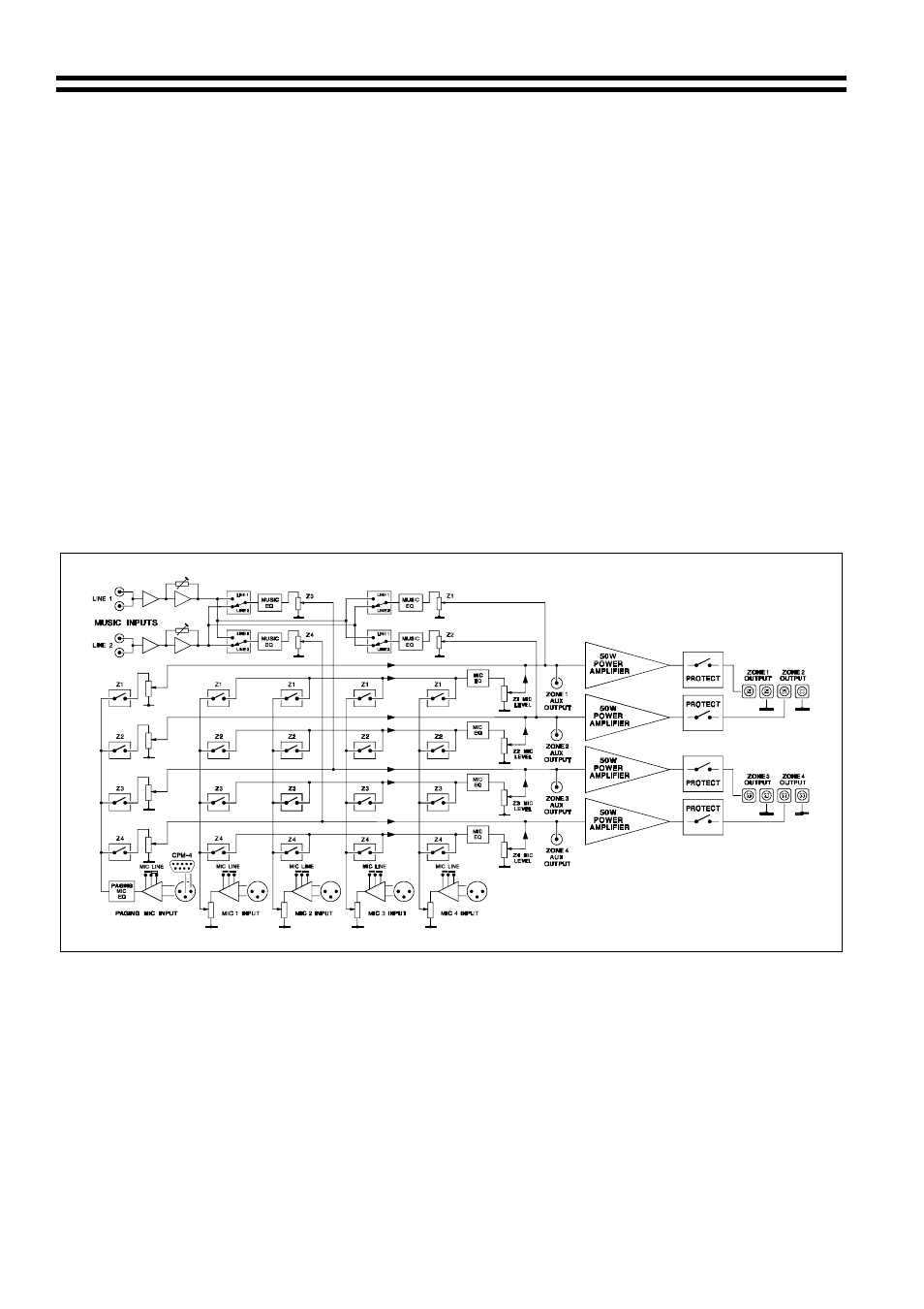
3 Schematic
Diagram
4 Installation
The Cloud Matrix 4 Mixer can be left free standing on a flat surface or be mounted in a
standard 19” equipment rack where it will occupy three units of rack space. The Matrix 4
Mixer is 160mm deep but a total depth of 235mm should be allowed to clear rear panel
connectors.
5 Microphone
Inputs
Four microphone inputs are provided; each of the four microphone amplifiers is an
electronically balanced, transformerless design configured for optimum low noise
performance. The input impedance is greater than 2k
Ω and is suitable for microphones in
the 200
Ω to 600Ω range. Inputs are via gold-plated 3-pin XLR type connectors with latch and
these are positioned on the rear panel.
16/12/02 V6.0