7 microphone equalisation, 8high pass filter – Cloud Electronics Matrix4 User Manual
Page 5
4
Matrix 4 I
NSTALLATION AND OPERATION MANUAL
Location of Jumpers J1, 2, 3 & 4
INPUT GAIN
SETTINGS
MICROPHONE INPUT
40dB GAIN
LINE INPUT
0dB GAIN
J1 MIC 1
J2 MIC 2
J3 MIC 3
J4 MIC 4
MIC 1
INPUT
MIC 2
INPUT
MIC 3
INPUT
MIC 4
INPUT
When setting the jumpers please ensure that you:
• Remove the mains cable from the rear of the product before removing the top panel.
• Only reassemble the unit using screws identical to the original parts.
7 Microphone
Equalisation
Separate two-band equalisation is provided for the composite microphone signals of each
and every zone, a removable tamperproof plate on the front panel protects these pre-set EQ
controls. The characteristics of the equalisation are optimised for the tonal correction of
speech signals and the HF (Treble) control provides ±10dB at 5kHz with the LF (Bass)
control ±10dB at 100Hz. A flat frequency response is achieved with the adjustment slots in
the horizontal plane.
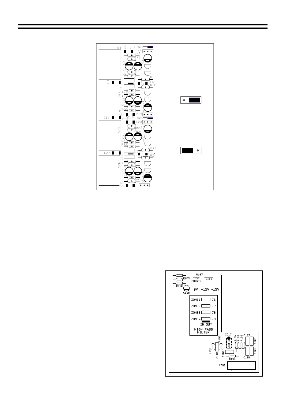
8
High Pass Filter
Location of Jumpers J6, 7, 8 & 9
All microphone signals pass through a simple
high pass filter; this reduces the effects of
breath blasts and handling noise. When used
with 100V line systems, additional filtering can
be introduced by setting the relevant internal
jumpers to the ‘IN’ position; these filters also
control the response of the music signals.
Jumper details follow:
J6 is for Zone 1
J7 is for Zone 2
J8 is for Zone 3
J9 is for Zone 4
When setting the jumpers please ensure you:
• Remove the mains cable from the rear of
the product before removing the top panel.
• Only reassemble the unit using screws
identical to the original parts.
16/12/02 V6.0