Comtech EF Data CRS-150 User Manual
Page 43
CRS-150 1:1 Redundancy Switch
Revision 2
Connector Pinouts
MN/CRS150.IOM
3–17
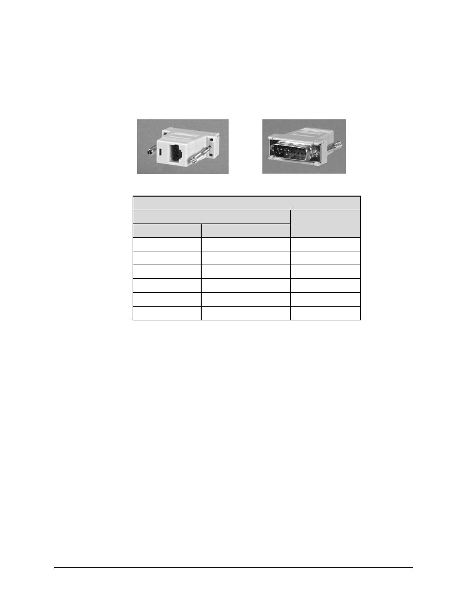
3.4.3 E1/T1 RJ-48 Connection via Balanced G.703 Interface Connector
For E1/T1 operation via an RJ-48 user interface, the optional CN-0000268 Adapter, shown in
Figure 3-2, may be purchased from Comtech EF Data to adapt the Balanced E1/T1 G.703
DB-15F connector on the front panel of the CRS-150 to an RJ-48 female connection.
CN-0000268 Adapter Pin Assignments
Pin #
Signal Name
RJ-48 (User Side)
DB-15M (Modem Side)
1 9 Tx+
2 1 Tx-
3 2 GND
4 11 Rx+
5 3 Rx-
6 4 GND
Note: Pins 7 and 8 on the RJ-48 side, and pins 5-8, 10, and 12-15
on the DB-15 side, are not used.
Figure 3-2. CN-0000268 DB-15M Æ RJ-48F Adapter for E1/T1 Operation
User Interface Side (RJ-48 F) Switch Interface Side (DB-15M)