Chapter 3. connector pinouts, Connector overview – Comtech EF Data CRS-280L User Manual
Page 33
Advertising
3–1
Chapter 3. CONNECTOR PINOUTS
3.1 Connector Overview
Front Panel View
R
e
a
r
P
a
n
e
l
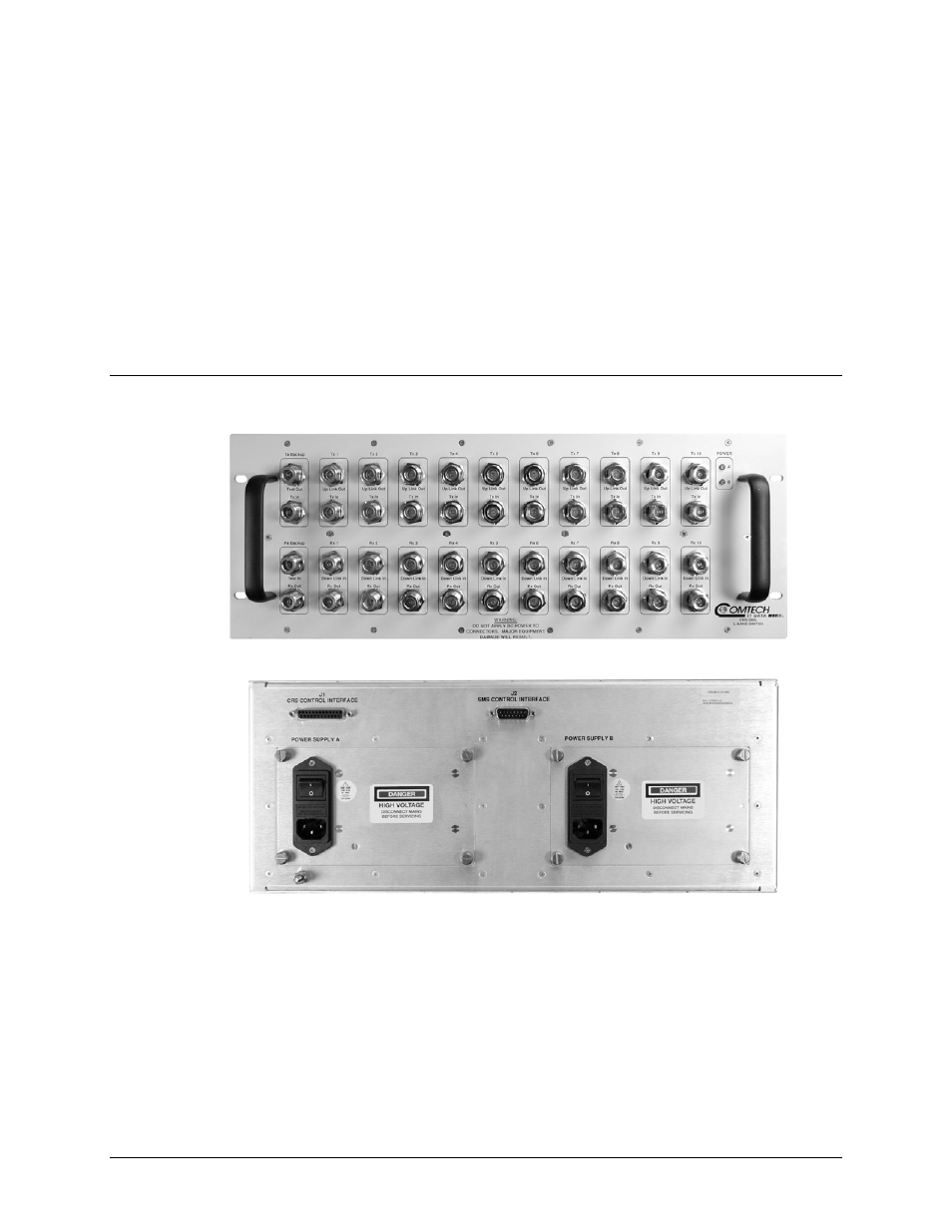
Rear Panel View (Standard AC Unit shown)
Figure 3-1. CRS-280L Connectors
The front and rear panels of the CRS-280L L-Band IF Switch are shown in Figure 3-1.
The front panel connectors provide all necessary to connect all equipment internal and external to
the 1:N redundancy setup. The rear panel connectors of the CRs-280L provide the control
connectors between the CRS-280L and its companion redundancy switch (e.g., CRS-300,
CRS-500, etc.).
On the next page, Table 3-1 summarizes these connectors, grouped according to location (front,
rear, or data interface) and service function.
Advertising