2 front panel connectors – Comtech EF Data CRS-280L User Manual
Page 35
CRS-280L L-Band IF Switch for 1:N Redundancy
Revision 1
Connector Pinouts
MN/CRS280L.IOM
3–3
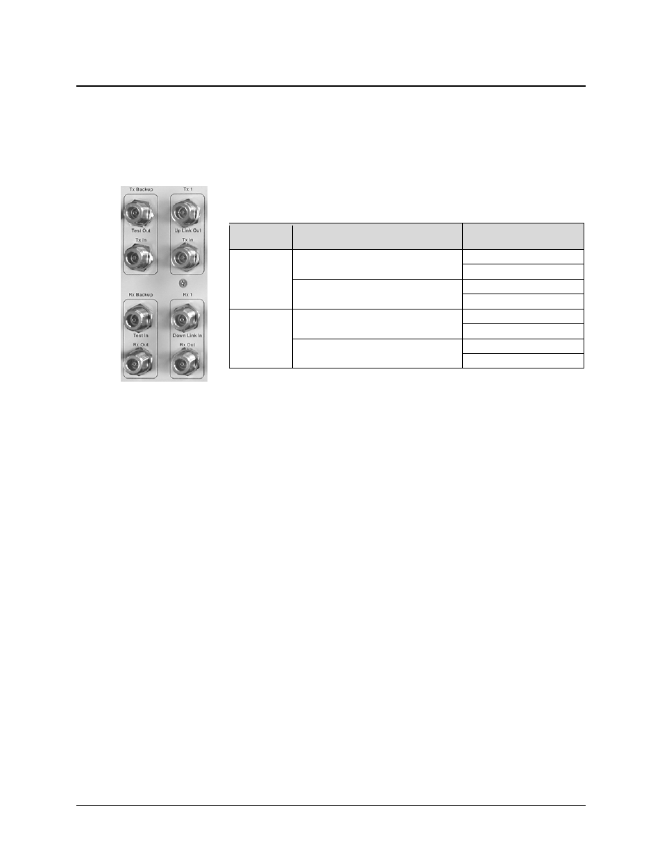
3.2 Front Panel Connectors
Unless otherwise noted, the connectors featured on the front panel of the CRS-280L are intended
for connection to all IF equipment internal and external to the 1:N redundancy setup.
3.2.1 Front Panel IF Connectors – Receive IF and Transmit IF, 50Ω Type ‘N’
Each Transmit IF and Receive IF port connector is a 50
Ω Type ‘N’ female
connector. Observe the following:
See Chapter 4. CABLES AND CONNECTIONS for complete details on IF cabling between
the CRS-280L and its companion redundant switches, redundant and traffic modems, and uplink
and downlink equipment.
IF Side
Connector
Pair
Connector Name
Transmit IF
Tx Backup (Tx Redundant)
Test Out
Tx In
Tx 1 through Tx 10 (Tx Traffic)
Up Link Out
Tx In
Receive IF
Rx Backup (Rx Redundant)
Test In
Rx Out
Rx 1 through Rx 10 (Rx Traffic)
Down Link In
Rx out