2 switch-to-modem if interface connection – Comtech EF Data CRS-180 User Manual
Page 65
CRS-180 70/140 MHz IF 1:1 Redundancy Switch
MN/CRS180.IOM
Cables and Connections
Revision 11
5–5
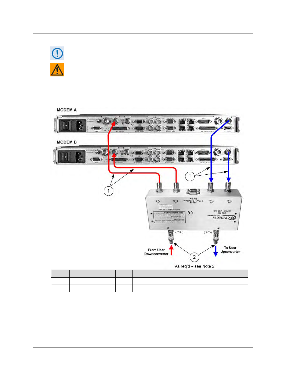
5.2.1.2 Switch-to-Modem IF Interface Connection
Excluding modems, the KT-0000159 1:1 Redundancy Kit (see Sect. 5.2.1) provides all
components shown in Figure 5-2.
EXAMPLE: The Tx IF from ‘MODEM A’ connects to the Tx IF port ‘J5 | Tx A’ on the
CRS-180; similarly, the Tx IF from ‘MODEM B’ connects to the Tx IF port ‘J6 | Tx B’
on the CRS-180.
The same logic applies for the Rx IF connections. It is important to note that failure
to observe this requirement will result in system malfunction.
Item
CEFD P/N
Qty
Description
1
PL/0946-1
4
IF Coax Cable, 50Ω
2
XF/BNC-MF-50-75
2
Transformer, 50-75Ω, 2-200 MHz, BNC, M/F
Figure 5-2. CDM-625/A Switch-to-Modem 70/140 MHz IF Connections (CEFD Kit
KT-0000159)