3 system connections – Comtech EF Data RRS11 User Manual
Page 17
RRS11 Solid-State Transfer Switch
Installation
MN-RRS11
2–3
Rev. 3
2.3
System Connections
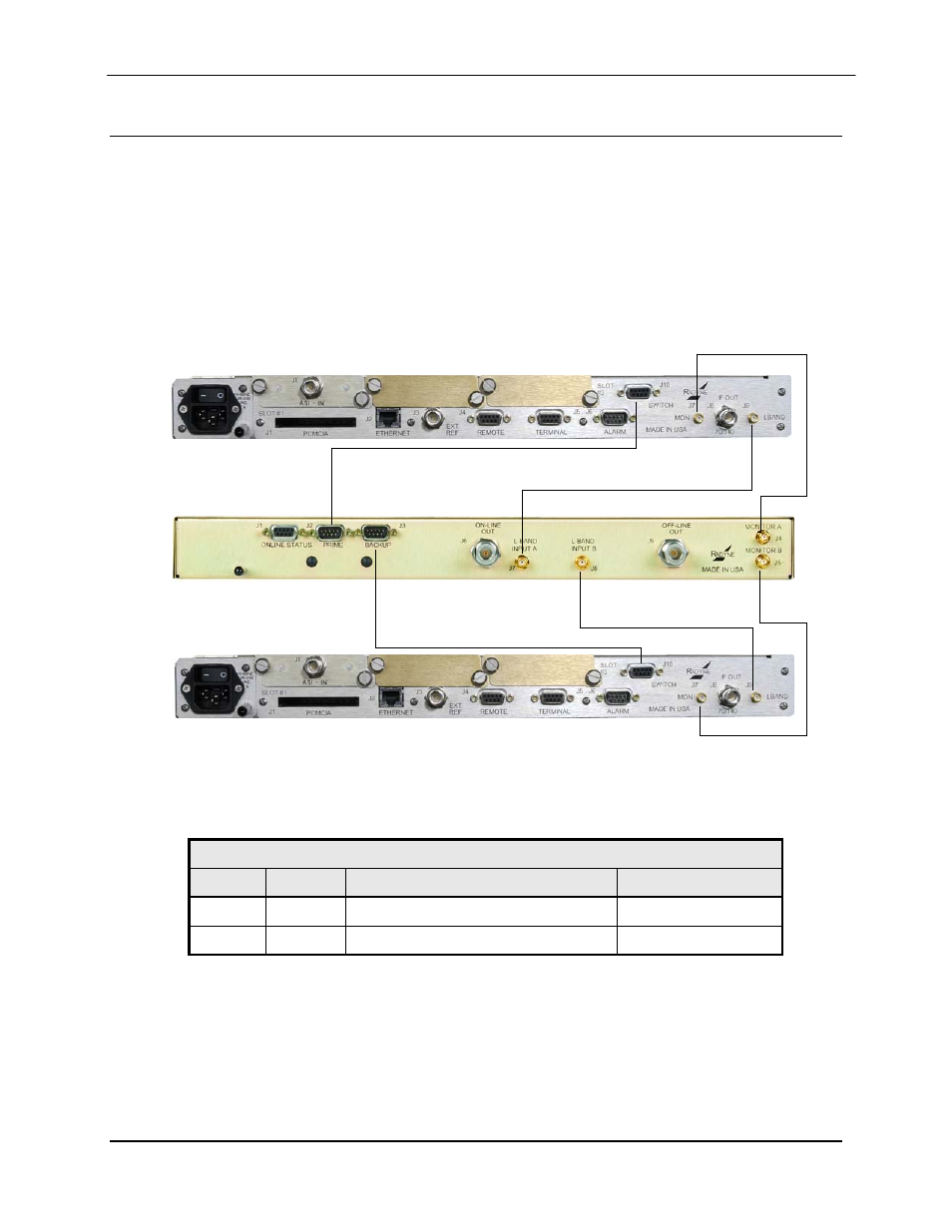
Figures 2-1 illustrates a typical setup with an RRS11-L and two DM240-PIIC modulators. Figure
2-2 illustrates a typical setup with RRS11 and two DM240XR modulators.
For initial Solid-State Transfer Switch setup and configuration, perform the following procedure:
1. Interconnect the units as shown in the figures below.
2. Proceed to Section 3, User Interface for information on the Solid-State Transfer Switch
controls and indicators.
Primary (A)
Backup (B)
Figure 2-1 Cable Connections between RRS11-L and Two DM-240-PIIC Units
Table 2-1 RRS11-L Interconnect Cable Part Numbers
Cable
Quantity
Description
Part Number
A
2
Control Cable (DB-9 Straight Cable)
CA/3677-1
B
4
L-Band Cable (50-Ohm SMA)
CA/5127AMAM-16