Comtech EF Data RRS11 User Manual
Page 23
Advertising
RRS11 Solid-State Transfer Switch
Operation
MN-RRS11
3–5
Rev. 3
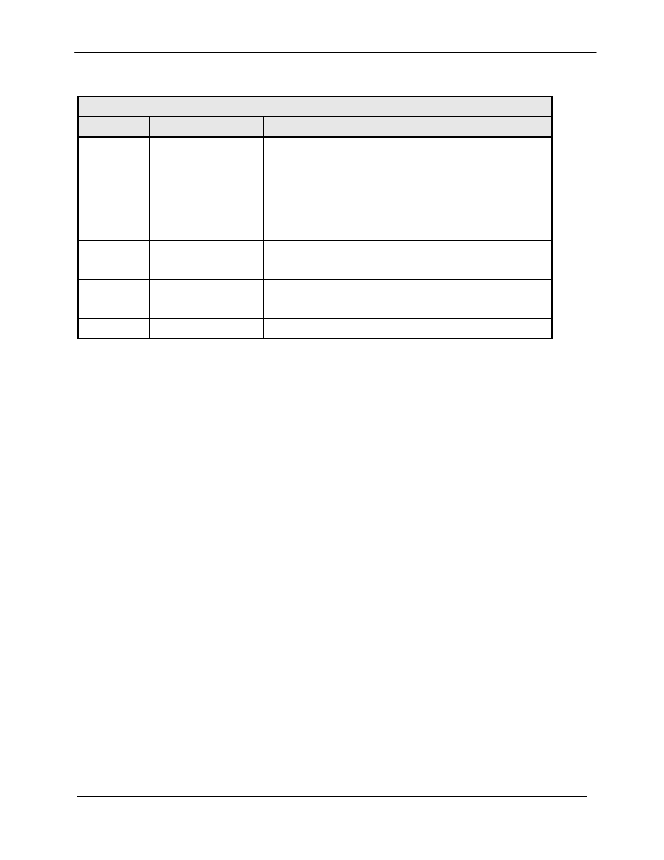
An additional 9-Pin D-Sub Connector is supplied for switch monitoring. The I/O on this connector
comes from a Form-C relay. The pinouts for the monitor connector is listed in Table 3-3.
Table 3-3. Switch Online Statue Pinout
Pin No.
Signal Name
Description
4
Signal Ground
Switch GND
1
Relay 1 NO
Relay Normally Open Contact
(Closed When the Backup Modulator is On-Line)
3
Relay 1 NC
Relay Normally Closed Contact
(Closed When the Prime Modulator is Online)
2
Relay 1 C
Relay Common Contact
7
Relay 2 NO
Relay Normally Open Contact
9
Relay 2 NC
Relay Normally Closed Contact
8
Relay 2 C
Relay Common Contact
5
NC
---
6
NC
---
Advertising